Hi Shaan, just a small question, the resistor powering the LED 's was chosen just to supply a few mA from what I have calculated, just asking because I dont realy want to use 33k especially 1/2W, it does get a bit hot at 56V, I do have on my hand 22k at 2W that I used before and it feels lot better.
Also regarding the diodes, are very close to each other ,the metal case connected to the catode is touching the other metal case of the next diode, very problematic.
Also the power resistors used in the CRC filtering, is the value provided in the BOM correct? Should these have a smaller value? Two in paralel would give 0.5 ohms at 10w, based and ohms law that means that one could use the power supply at under 5A per rail because any more would cause more than 10 w to be dissipated on those resistors ( P=R x I square )
I am asking just to make sure I am puting the right components on the board, I realy dont want to desolder and resolder because its difficult to do it on a plated hole and at this thickness, I dont want to damage the pads.
Thanks in advance,
Florin
Last edited:
Hi Shaan, just a small question, the resistor powering the LED 's was chosen just to supply a few mA from what I have calculated, just asking because I dont realy want to use 33k especially 1/2W, it does get a bit hot at 56V, I do have on my hand 22k at 2W that I used before and it feels lot better.
Hi Outtek.
The 33K resistors on each side with 56V supply dissipate less than 100milliwatt. So 1/4W or 1/2W resistors should be fine in long term. I think it would be better to increase the 4K7 1W resistors to 5K6 1W coz they do dissipate about 670milliwatt with the default value and do get pretty warm.
Also regarding the diodes, are very close to each other ,the metal case connected to the catode is touching the other metal case of the next diode, very problematic.
Yes you are right the diodes are indeed placed a little too close. I think I will re-arrange them with some place to breath in the next set of boards. Thank you for the note and I am sorry for the hassle.

Also the power resistors used in the CRC filtering, is the value provided in the BOM correct? Should these have a smaller value? Two in paralel would give 0.5 ohms at 10w, based and ohms law that means that one could use the power supply at under 5A per rail because any more would cause more than 10 w to be dissipated on those resistors ( P=R x I square )
The values are correct in the BOM, but are not absolutely fixed. Maximum steady state or continuous current per rail with the default resistor value is 4A (not the peak/transient current). So if your application requires more bias current then you can just replace the 1R resistors with 0.82R or 0.68R accordingly while keeping the dissipation to less than 10W.
The above solution may seem counterproductive because a lower resistor value in CRC directly means a lower filtering of the ripples. But here's the thing. I guess you don't plan to build an amplifier running from +/-56V and dissipating 280W of heat per channel (2.5A bias). I mean typically pure class-a push pull amplifiers have a maximum PSU rail requirement of +/-25V or less. So the voltage rating required for the main capacitors come down to 35V. And now you can increase the capacitance from 15000uF per capacitor to 22000uF or even 33000uF and have the same filtering as before while the new capacitors still fitting in the same footprints.
If the amplifier is unique and indeed needs a high steady state current at a higher than normal rail voltage then I suggest using one PSU per channel.
I am asking just to make sure I am puting the right components on the board, I realy dont want to desolder and resolder because its difficult to do it on a plated hole and at this thickness, I dont want to damage the pads.
Thanks in advance,
Florin
No problem at all! Thanks to you for posting. I hope the above helps.
shaan
Hi Shaan, tha ks for replying, I will use in this case probably a slightly lower value, i do have the metal plate type but only 0.22 ohms, quite a low value, regarding the diodes I found some in full plastic case, similar performance to the MUR1560, also some schottky type diodes: much smaller forward voltage and less heat but these can only tolerate 45v reverse voltage .
Thanks,
Florin
Thanks,
Florin
Stupid question but better safe than sorry. Can I connect 2 CT transformers to one board?
In CT mode, no.

I was unlucky with the shipment. My 4 boards have returned ti India because of the crappy Norwegian postal service. Shaan will send them back when he gets them but it takes time. Are there any from Norway that has a couple of spare boards so I can get them and return some when mine has arrived sometime this Autumn?
Shaan,
Quick question regarding the 8 diodes for dual secondary use. As mentioned earlier by Outtek, the metal casing on the diodes are extremely close and will rub against each other if mounted straight.
What are the cooling requirements for these? I was considering mounting them to the baseplate of the chassis and possibly fanning them out to separate them. Another option would be mounting one on top and the next on the bottom, but not sure that would be acceptable cooling wise. Would a small individual heat sink attached with thermal tape be sufficient for one diode?
The other option I'm considering is to purchase the diodes in the full-pack version so there is no exposed metal casing: MURF1560G ON Semiconductor | Discrete Semiconductor Products | DigiKey. I would assuming this is a viable alternative?
Thanks.
Hi Loafimus.
Mounting them to the baseplate with mica or other insulation will be more than sufficient to cool them under heavy load. This way no extra heatsinks will be necessary.
Yes you can use the full plastic body diodes without any problem and they won't need extra insulation from chassis.
Sorry for late reply. Thanks for notifying about the diode placement issue. I will correct it in the next set of boards.
shaan
Quick note, I found some nice chassis mounted resistors to use for the 5W ones that I was having a difficult time sourcing in the correct footprint:
5 (Five) Vishay Dale 0.5 Ohm 25W Power Resistors 1% P/N: RH025R1000FC02 | eBay
I'll just mount one off to each side and run some leads to them.
5 (Five) Vishay Dale 0.5 Ohm 25W Power Resistors 1% P/N: RH025R1000FC02 | eBay
I'll just mount one off to each side and run some leads to them.
Shaan,
What resistors do you suggest for R13, R15, R16, R14? The wirewounds I bought don't fit.
Vertical mount ceramic. 10-12mm pin pitch
Hi Shaan,
I’d like to get into the next GB, are you still planning for September?
Thanks
Probably. Depends on how many people join. I can print the next batch with at least 50 confirmed PCBs ordered.
Probably. Depends on how many people join. I can print the next batch with at least 50 confirmed PCBs ordered.
Very good, thanks.
I’d be in for 4 boards
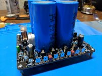
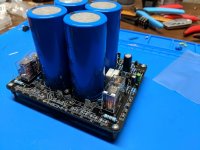
Got the PSU stuffed for the most part except for the LEDs and diodes. The diodes will be mounted under onto the base plate and the LEDs will have a lead to the front panel.
Good looking board Shaan.
Good looking board Shaan.
Attachments
Got the PSU stuffed for the most part except for the LEDs and diodes. The diodes will be mounted under onto the base plate and the LEDs will have a lead to the front panel.
Good looking board Shaan.
Looking good
Loafimus,
What size (uF) CDE caps are you using?
- Home
- Group Buys
- PeeCeeBee PSU GB