Very nice boards...
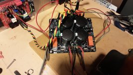
PSU running fine! 1.5 years after receiving the boards . These boards are really good quality and solid. Everything fit perfectly, following shaan's BOM. This is powering a pair of Apex Audio AX-14 amps at the moment and works great.
Is there an advantage to dual secondaries? I wired it for the center tap connections mainly to use less diodes but my transformer has dual.
PSU running fine! 1.5 years after receiving the boards
. These boards are really good quality and solid. Everything fit perfectly, following shaan's BOM. This is powering a pair of Apex Audio AX-14 amps at the moment and works great. Is there an advantage to dual secondaries? I wired it for the center tap connections mainly to use less diodes but my transformer has dual.
Attachments
PSU running fine! 1.5 years after receiving the boards

")
You were in the very first V4 GB. Don't tell me the boards are on the shelf for 3 years now!
Is there an advantage to dual secondaries? I wired it for the center tap connections mainly to use less diodes but my transformer has dual.
Nothing special about dual secondaries. CT with 4 diodes is just fine.
V4 amps were built a couple years ago and are still at the top of my favorites list. An excellent amp by any comparison.
You were in the very first V4 GB. Don't tell me the boards are on the shelf for 3 years now!
hi .. are there reprints of this pcb? thank you
Hello.
Boards will again be printed if enough interest arises. I can get another print if total required number of boards reach 40.
Hello.
Boards will again be printed if enough interest arises. I can get another print if total required number of boards reach 40.
Hi Shaan,
Hope all is well.
I would like to order 6 x PSU boards for the next GB.
Also, can't wait for the V5!
Cheers,
Daniel
Hi Shaan, just a small question, if the board doesnt see AC it will not power up the relays? I am asking because I have populated the board except the rectifier diodes and I was feeding the board from a separate bridge rectifier. Would that be a normal behaviour?
Thanks, Florin
Thanks, Florin
Hi Outtek.
The relays will not trigger if AC is not present on board. You can get around this problem easily.
There is one diode between R5 and R7 on the left, and one between R6 and R8 on the right. Connect one of the AC outputs from the transformer to the anode of the left side's diode, and to the cathode of the right side's diode. Take care not to create solder bridges as these diodes are closely placed with the resistors.
Or,
If there are no power rectifiers present on board, connect the AC outputs to anode of D1 Rectifier, and cathode of D2 Rectifier.
In either case, use 1Kohm 0.25W resistors in series with the AC connections. The resistors should be as close to the transformer's AC outputs as possible to prevent any chance of a short connection between the AC output and other nodes.
Last edited:
Hi Shaan, managed to get the board done but when the relays engage it does it like in a vibrating/oscillating way not a swift switch as one would expect, the two resistors calculated for 56v ( 12v relay wit 220 ohm coill, I ended up with a 390ohm resistor this way )get very hot, the voltage across the coil is 12.6v, I do not believe that is normal. Is there an issue with my build?
Thanks, Florin
Thanks, Florin
- Home
- Group Buys
- PeeCeeBee PSU GB