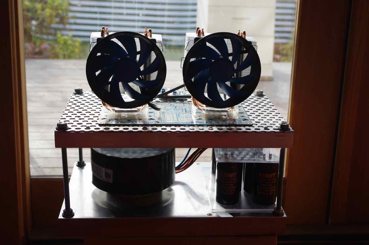
I wish the cpu coolers didn't have the ends of the heat pipes exposed. Maybe I could make a cap to clean up the look a bit...
I could make a Delrin or PTFE cap, remnant pieces of both are inexpensive on eBay.
So many ideas, hahah
Hi Gab, all of them don't have exposed end pipes, like be quiet! Dark Rock Pro 4 that looks nice..but it seems that it comes with a price tag.
Maybe better idea is to fabricate something yourself
")

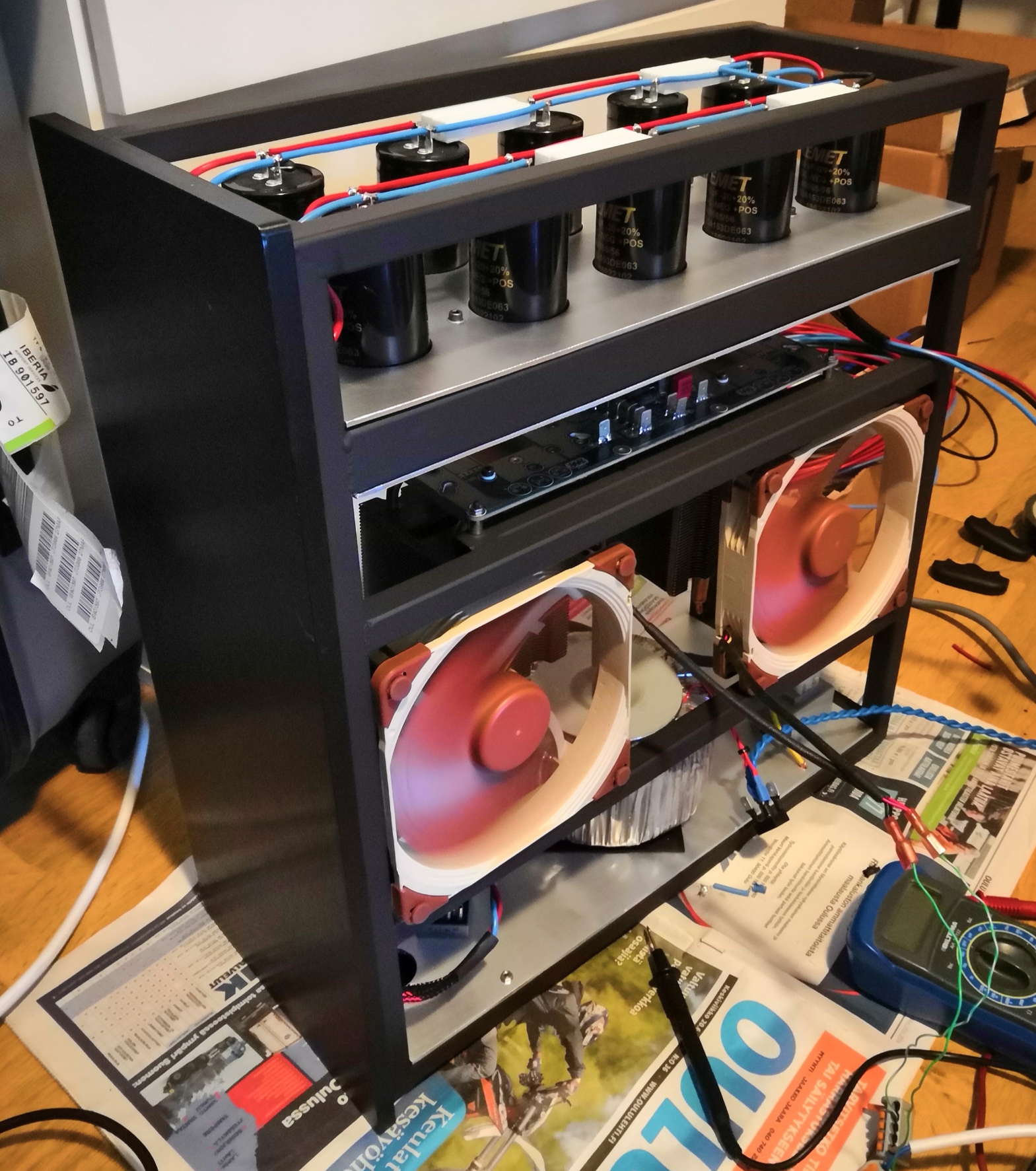
Just wanted to note that Juntuin got his Alpha BB monoblocks to make music! He says it is absolutely noise free on 97dB sensitive speakers. Beautiful custom welded steel frame (nice to have a pro-welder for a GF!).
Aksa Lender P-mos Hybrid Aleph (ALPHA) Amplifier
There are still more Alpha 20 and Alpha BB PCB's available in case anyone else wants to build them.
More news is that the Mr Evil cap Mx board by jkeuterman works really well as Vunce found out:
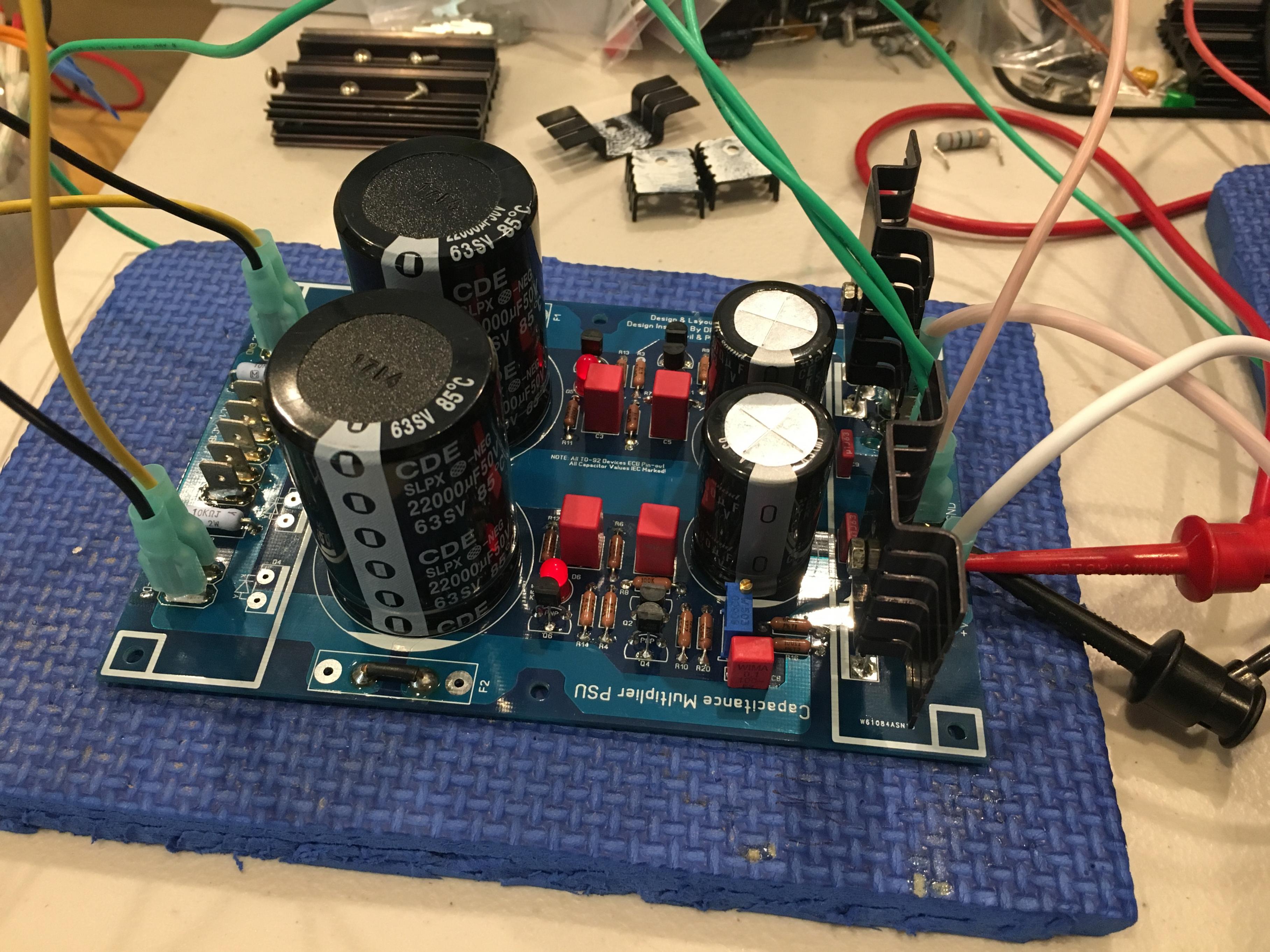
It only has a 1.5v drop so doesn't get too hot.
Here is Wtl's BB at the layout stage:
Here is jwarch's Alpha 20 up and running and sounding great:

Aksa Lender P-mos Hybrid Aleph (ALPHA) Amplifier
There are still more Alpha 20 and Alpha BB PCB's available in case anyone else wants to build them.
More news is that the Mr Evil cap Mx board by jkeuterman works really well as Vunce found out:
It only has a 1.5v drop so doesn't get too hot.
Here is Wtl's BB at the layout stage:
Here is jwarch's Alpha 20 up and running and sounding great:
Last edited:
Looks like there have been several builds of Alpha 20 going on. I encourage folks to post build questions in this thread rather than the thread on SS forum which is more for discussing the amp design, performance, etc.
Last question was whether or not the AMP 2-position 2.54mm pitch by TE Connectivity, connector for the audio input will fit a female plug here:
3-641237-2 TE Connectivity / AMP | Mouser
Yes, I think those are the mating pair. Although, someone who has actually ordered it would be better person to answer. I personally use JST jacks and plugs.
Looks like there have been several builds of Alpha 20 going on. I encourage folks to post build questions in this thread rather than the thread on SS forum which is more for discussing the amp design, performance, etc.
Last question was whether or not the AMP 2-position 2.54mm pitch by TE Connectivity, connector for the audio input will fit a female plug here:
3-641237-2 TE Connectivity / AMP | Mouser
Yes, I think those are the mating pair. Although, someone who has actually ordered it would be better person to answer. I personally use JST jacks and plugs.
X,
No problem I will do that for any future questions.
That you for the clarification. Do you have a part number for the JST jack and plug?
Brad
X,
No problem I will do that for any future questions.
That you for the clarification. Do you have a part number for the JST jack and plug?
Brad
I just google for “JST 2.54mm pitch connector”. I find it most convenient to get the kit.
60 sets 2p 3p 4 pin 5pin xh 2.54mm Pitch Terminal Housing Pin Header terminal Connector with box connector-in Connectors from Lights & Lighting on Aliexpress.com | Alibaba Group
Or
Amazon.com: 750 Pieces 2.0mm JST-PHR JST Connector Kit. 2.0mm Pitch Female Pin Header, JST PH - 2/3/4 Pin Housing JST Adapter Cable Connector Socket Male and Female, Crimp DIP Kit.: Computers & Accessories
Having good crimper tool is key if you plan on using this long term for all your projects.
IWISS XH2.54/3.96, PH2.0, PX, JST, Molex, Dupont Terminal Crimping Tool SN-01BM Rachet Crimper AWG28-20 (0.08-0.5mm 2) - - Amazon.com
I have been getting a lot PM's and emails from members regarding details of building the Alpha 20 - I just want to remind folks to read this thread for lots of good tips and suggestions and as the main source for BOM and updates to parts etc.
One main suggestion to make it easier is to simply not install the trim pots. Use nominal value fixed resistors and the amp will be adjustment free and have close to 0v DC offset. Replace pot R105 with a 1k+47R series resistors (1%).
Use the schematic recommended 0.33R and 0.33R in parallel values for R131/R132, respectively for 1.7amp bias. Use 0.47R and double 0.47R for R131/R132, respectively for 1.3amp bias current.
Xrk,
I am building one channel of Alpha 20W and I powered up the amp after the build.
First up - dc offset is around -60mV. I have only R105 pot. I am assuming adjusting this would adjust the offset? The offset dropped to around -50mV as the heatsink started gaining temperature but one of the output transistor was not attached to heatsink properly and and was getting very hot. Hence I stopped the test. I have fixed the output transistor and hope it is making proper contact with heatsink now. Before testing again, I wanted to check with you if I am right in assuming the pot adjusts DC offset.
Secondly, at start up, the DC offset shoots to high value before settling close to zero DC offset which was reported by other builders as well. I am guessing without the delay circuit, it is not possible to avoid this. If you can come up with some circuit which would work with amplifier DC supply itself (rather than another board with different supply), it would be good solution. I am not sure you are planning something for this.
Thanks
Balaji
Xrk,
I am building one channel of Alpha 20W and I powered up the amp after the build.
First up - dc offset is around -60mV. I have only R105 pot. I am assuming adjusting this would adjust the offset? The offset dropped to around -50mV as the heatsink started gaining temperature but one of the output transistor was not attached to heatsink properly and and was getting very hot. Hence I stopped the test. I have fixed the output transistor and hope it is making proper contact with heatsink now. Before testing again, I wanted to check with you if I am right in assuming the pot adjusts DC offset.
Secondly, at start up, the DC offset shoots to high value before settling close to zero DC offset which was reported by other builders as well. I am guessing without the delay circuit, it is not possible to avoid this. If you can come up with some circuit which would work with amplifier DC supply itself (rather than another board with different supply), it would be good solution. I am not sure you are planning something for this.
Thanks
Balaji
First, congrats on a successful build. The Alpha 20 is an easy amp to get working. Secondly, 50mV is not bad but it sort of depends on the whole chain of components all balancing out. I would suggest removing R105 and setting it to 1050ohms and replacing it (unless you did that already). Or replace it with a 1k+47R fixed resistors in series. If you do leave it in and adjust it, do not adjust it too far from 2mA current through R5. The LTP (actually long necked pair in this case) current should be about 2mA total. If one of your MOSFETs was not firmly attached, the Vgs will be off. Try again and if you are within 25mV that’s normal. It should be stable relatively with temp.
We have discussed the turn on thump. If you wish to avoid it, use a delay relay on output ($5 on eBay or Ali) or use a cap Mx with say a 3 second slow ramp up voltage.
Good luck!
Hello XRK,
Thanks for the response. I gave it a try again after fitting transistors properly. The DC offset is still at -50mV and fluctuates anywhere from -60mV to -45mV.
I connected to speakers and heard it is playing fine. After 15 minutes of playing, the heatsinks are moderately warm. I feel the heat is more compared to earlier amplifier playing there (Hiraga 30W) but need to check it for longer duration. May be I need to add a fan to the place where this amplifier will reside since there is no air circulation at all. It may get very hot there.
Next step is to get the delay circuit, get the fans for cooling and then let it burn before judging the sound. Initial impression seems like warm sound but it's too early to judge.
Thanks for all your efforts XRK, Hugh and JPS.
Thanks
Balaji
Hi X,
I am gathering parts for the 20W version and want to use parts I already have, just wondering:
1. If it is okay to use RN55 resistors (0.125W) instead of the MBA series (0.4W) resistors in the BOM? Is the lower power rating an issue?
2. For C111, if it is okay to use 2200uF 50V cap instead of the 1000uF 50V cap as in the BOM?
3. Is a dual 22Vac 400W transformer adequate for the build?
Thanks
Tim
Hi X,
I am gathering parts for the 20W version and want to use parts I already have, just wondering:
1. If it is okay to use RN55 resistors (0.125W) instead of the MBA series (0.4W) resistors in the BOM? Is the lower power rating an issue?
Yes, except for the large 3W power resistors at the output stage - I highly recommend Panasonic ERX 3W units. For the feedback resistor, use a higher power rating if possible as thermal effects can cause distortion.
2. For C111, if it is okay to use 2200uF 50V cap instead of the 1000uF 50V cap as in the BOM?
Yes, that’s fine.
3. Is a dual 22Vac 400W transformer adequate for the build?
Yes, that’s perfect actually since an 18vac sags too much under Class A load.
Thanks
Tim
Aive just reminded me of a mod that was developed for the BB that seems to have gotten lost unless you read through the whole thread:
https://www.diyaudio.com/forums/sol...id-aleph-alpha-amplifier-206.html#post5420594
https://www.diyaudio.com/forums/sol...id-aleph-alpha-amplifier-206.html#post5420594
- Home
- Group Buys
- Aksa Lender P-mos Hybrid Aleph (ALPHA) Class A Amp GB