This is just listed for information should others also experience issues with oscillation despite the update(s), you might want to take a closer look at the thermal pads that you are using and the capacitive coupling of these (DA). Maybe change to a different type will eliminate the problem.
Background:
Finally got to build-up two of the boards bought in the spring last year rev.1
Actually adjusting the boards went without any issues at all, stable and easy setup, everything as described.
Then on to the actual test with load - where I despite using the updated boards and proper grounding of the heat sinks, experienced the oscillation described in #583
Initially I thought it was an unstable SMPS, but that really just reacted to the high peak loads by entering protect mode.
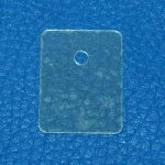
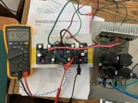
After different attempts at tracking down the problem I finally decided to run common source on the heat sink - thus removing my ceramic(!) heat pads. The amplifier is now completely stable and I did measure just over 40v peak into the small Apogee's (3.5ohm) without hiccups.
The capacitive coupling to the Lateral Mosfet's is known to be critical, so it wasn't entirely surprising, when looking for something out of the normal in my build which could cause the instability.
Doing a common source direct mount configuration is NOT for the beginner and even the experienced might get caught out by old habit's, when chassis is "output" and each channels PSU's (incl GND) are to be kept separate.
I own active ATC monitors and they are a perfect example of a commercially available construction configured this way.
Thanks a lot for the design and for the support Shaan!
I am now happily moving on to finalize the four mono-blocks as soon as I receive the 4x 630G SMPS from Sami (Cresnet)... pictures to follow
Background:
Finally got to build-up two of the boards bought in the spring last year rev.1
Actually adjusting the boards went without any issues at all, stable and easy setup, everything as described.
Then on to the actual test with load - where I despite using the updated boards and proper grounding of the heat sinks, experienced the oscillation described in #583
Initially I thought it was an unstable SMPS, but that really just reacted to the high peak loads by entering protect mode.
After different attempts at tracking down the problem I finally decided to run common source on the heat sink - thus removing my ceramic(!) heat pads. The amplifier is now completely stable and I did measure just over 40v peak into the small Apogee's (3.5ohm) without hiccups.
The capacitive coupling to the Lateral Mosfet's is known to be critical, so it wasn't entirely surprising, when looking for something out of the normal in my build which could cause the instability.
Doing a common source direct mount configuration is NOT for the beginner and even the experienced might get caught out by old habit's, when chassis is "output" and each channels PSU's (incl GND) are to be kept separate.
I own active ATC monitors and they are a perfect example of a commercially available construction configured this way.
Thanks a lot for the design and for the support Shaan!
I am now happily moving on to finalize the four mono-blocks as soon as I receive the 4x 630G SMPS from Sami (Cresnet)... pictures to follow
Last edited:
This is just listed for information should others also experience issues with oscillation despite the update(s), you might want to take a closer look at the thermal pads that you are using and the capacitive coupling of these (DA). Maybe change to a different type will eliminate the problem.
Background:
Finally got to build-up two of the boards bought in the spring last year rev.1
Actually adjusting the boards went without any issues at all, stable and easy setup, everything as described.
Then on to the actual test with load - where I despite using the updated boards and proper grounding of the heat sinks, experienced the oscillation described in #583
Initially I thought it was an unstable SMPS, but that really just reacted to the high peak loads by entering protect mode.
After different attempts at tracking down the problem I finally decided to run common source on the heat sink - thus removing my ceramic(!) heat pads. The amplifier is now completely stable and I did measure just over 40v peak into the small Apogee's (3.5ohm) without hiccups.
The capacitive coupling to the Lateral Mosfet's is known to be critical, so it wasn't entirely surprising, when looking for something out of the normal in my build which could cause the instability.
Doing a common source direct mount configuration is NOT for the beginner and even the experienced might get caught out by old habit's, when chassis is "output" and each channels PSU's (incl GND) are to be kept separate.
I own active ATC monitors and they are a perfect example of a commercially available construction configured this way.
Thanks a lot for the design and for the support Shaan!
I am now happily moving on to finalize the four mono-blocks as soon as I receive the 4x 630G SMPS from Sami (Cresnet)... pictures to follow
Hi Norgaard.
Thanks for sharing your findings and I hope it helps anyone dealing with the same problem.
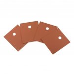
If possible, see if you can try mica or silicone-glassfiber pads (which result in more capacitive coupling between mosfet back and heatsink ground). These mosfets really like some constant small capacitance (few tens of pF) to ground at their sources, as you can see that with them mounted directly on heatsink body which is insulated from chassis ground, the total surface area is much larger and results into some adequate value that loads the source nodes just enough so that no oscillation occurs. I measured the capacitance between two 300mm heatsinks separated 5cm with air in between to have 20-25pF, and the back of mosfet to heatsink body when using sil-pads to have almost 40-50pF, and with thermal paste soaked thin mica to have almost 100pF! Ceramic pads are of considerable thickness which cannot create a large enough parasitic capacitor between the mosfet backs and a grounded heatsink, compared to even heatsink body to chassis ground capacitance with air dielectric which solved the case for you.

Last edited:
Hi Shaan,
That is very helpful info, but it also had me recheck why I had success . Since I actually didn't mount it that way
In my POC I have no ground connection to chassis and heatsink at all - entire housing is all connected to common source for the 4 Exicon's
The problem behind the problem, is that the devices are very sensitive to source inductance when running multiple set's, so even the short pcb traces between the mosfets are problematic.
Key is to shunt out the inductance, with the thermal pads and isolation it is shunted by series connections of basically: small inductor->capacitor->small inductor
But when mounted directly w.o. isolation it's shunted by the heatsink, 10mm alu slab with ribs, which is a very poor inductor (good shunt).
In the final build-up I will mount the V4H directly on it's own block of aluminium, which is then mounted electrically isolated from the chassis and main heatsink.
N.B: I have sent you an email.
That is very helpful info, but it also had me recheck why I had success
. Since I actually didn't mount it that way In my POC I have no ground connection to chassis and heatsink at all - entire housing is all connected to common source for the 4 Exicon's
The problem behind the problem, is that the devices are very sensitive to source inductance when running multiple set's, so even the short pcb traces between the mosfets are problematic.
Key is to shunt out the inductance, with the thermal pads and isolation it is shunted by series connections of basically: small inductor->capacitor->small inductor
But when mounted directly w.o. isolation it's shunted by the heatsink, 10mm alu slab with ribs, which is a very poor inductor (good shunt).
In the final build-up I will mount the V4H directly on it's own block of aluminium, which is then mounted electrically isolated from the chassis and main heatsink.
N.B: I have sent you an email.
Last edited:
Hi Per.
I agree, you either get inter-source inductance lower, or increase capacitive loading and get it shunned. Both ways work, but I asked you to try the second way very much because you didn't, as mentioned in post 1501, and that is okay since you are already aware of its effects. What matters is whether your current setup works without hiccups or not, and I'm happy to know it does.
If I'm not wrong, in case of mounting on a grounded heatsink via thin thermal pads it would be small capacitor (mosfet parasitics) -> inductor (mosfet source and PCB trace) -> small capacitor (mosfet source to heatsink ground, pads acting as dielectric). I have never tried the thick ceramic insulators, so thank you for letting us know with experiments why those might not be a good idea for this amp and how a stable setup can be done without using any thermal insulation for the mosfets at all.
I have checked your email. Thank you for the much valuable information!
Can't wait to see your final build!
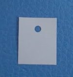
I have used this kind with success:
Silikonisolatoren
Silikonisolatoren
Attachments
Thks Vunce, i received everything perfectly.Excellent!!
I could have thrown in a couple of BAV's if i knew
Good choice, the V4H is one fine amplifier.
Happy Building
About bav21 i found it on a store here in Portugal. [emoji3]
Hello Shaan , i received the pcbs from Vunce! everything is ok!
Glad to know you got the boards, and also the diodes.
another thing can i buy mje340/mje350 instead kse340/kse350?
thks!!
Yes.
https://www.diyaudio.com/forums/members/shaan.html
i want to buy 4 pcb. Is this product available anymore?
i want to buy 4 pcb. Is this product available anymore?
- Home
- Group Buys
- PeeCeeBee V4H GB