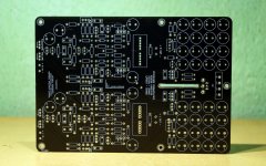
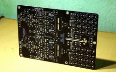
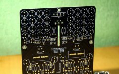
Attachments
when will you be able to order pcb pre
Hi Deps.
I will start a new GB for the preamplifier soon (probably by early July). All details will be posted there. I will post an update here as the thread goes online.
Thanks
Looks very nice Shaan
I like your “signature” control. This should be fun!
Thanks.
Yes, it is fun. It allows to vary the feeling of the music as per one's taste, mood, time of day, season, source material, speakers, amplifier and so on.
At one end of the knob it can make the system extremely transparent with about 0.0001% minimum distortion, and at the other end it can make it extremely warm by masking the system with about 1% maximum distortion typical of low powered SE Class A amplifiers. One only needs to find the positions of the knob that sing in harmony with the rest of the system (which will vary from one listener to the next) - i.e. a truly personal preamplifier.
As you would have guessed, there is a sweet spot in this control for (I think) every moment, mood and music.
p/s:
Did I tell you that it is also a fantastic headphone amplifier?

wow! thats nice feature-full pre/HPA. I will in for 1 whenever GB starts.
Thanks man.
Tell me you dont have any "unobtaniums" in your design.
Naaaahhh... there isn't one. I like the concept of emergence.
Earnestly looking forward to reading about your 'signature' circuit, its evolution and implementation.
It is fairly obvious why you wanted to go in for something 'out of the box' like this...rather than the (more laudable?) "straight wire with gain" stuff. Yeah, this is a real world that we live in... in spite of all the measurements that many of us are fond of making in the intervals between enjoyable bouts of listening!
Happy to note that the preamp uses regular stuff, and no exotica.
Do accept my hearty congratulations for your original thinking!
Earnestly looking forward to reading about your 'signature' circuit, its evolution and implementation.
It is fairly obvious why you wanted to go in for something 'out of the box' like this...rather than the (more laudable?) "straight wire with gain" stuff. Yeah, this is a real world that we live in... in spite of all the measurements that many of us are fond of making in the intervals between enjoyable bouts of listening!
Happy to note that the preamp uses regular stuff, and no exotica.
Do accept my hearty congratulations for your original thinking!

I tried to make it so that the preamp does Not bind the listener to a preset sonic character and force everything else in the system including the listener to accommodate with that. From a frugal point of view, I myself find the idea appealing and applicable for my own 100% DIY system (the veroboard prototype preamp has been in my system since lockdown started in March, and I have been enjoying it throughly), and I hope others will find it equally enjoyable in their own systems, soon.
Thanks for the kind words.
Phase change pads
Months ago i ordered these thermal pads on Mouser.
https://www.mouser.es/datasheet/2/433/Phase_Change_Wakefield-Vette_Data_Sheet_Rev_2-1369505.pdf
Just now i'm discovering it's something exotic , someone with an experience on this material ? after an hour on internet nothing ....
Months ago i ordered these thermal pads on Mouser.
https://www.mouser.es/datasheet/2/433/Phase_Change_Wakefield-Vette_Data_Sheet_Rev_2-1369505.pdf
Just now i'm discovering it's something exotic , someone with an experience on this material ? after an hour on internet nothing ....
Though my experience with Wakefield-vette thermal pads is nil, a friend familiar with commercial operations tell me that they are very convenient and effective in production environments. He is unable to help with comparative thermal properties, but vouches that these score when it comes to the many negative aspects of conventional thermal compounds and their dispensing, especially in production lines.
Personally I feel that these days it is the fashion to go in for exotic thermal pads. Surely they might contribute to better thermal efficiencies. But sadly some of the device packages (IMHO) are not designed well for effective mounting.
In virtually all DIY situations, I have observed that the best thermally effective mounting is to clamp the device with a somewhat large thick aluminium L- or U-section and a couple of screws to the heatsink , with thin Kapton heatsink tape stuck on the heatsink and a smear of good thermal compound (Arctic Silver!) over that, and not go in for the conventional screw-washer mounting, or the commercial type heatsink pads.
Now my heatsinks are drilled ,place these phase- change is the easiest thing .
Major problem is the delay of getting other products . The only fast shipment is Mouser paying a minimum 60 € and here in Barcelona with 4 million people the last electronic shop is quite closed. A letter with 5 capacitors takes 4 weeks to come from Germany to Spain .Thanks
Major problem is the delay of getting other products . The only fast shipment is Mouser paying a minimum 60 € and here in Barcelona with 4 million people the last electronic shop is quite closed. A letter with 5 capacitors takes 4 weeks to come from Germany to Spain .Thanks
I will take note of your advice for the future. I bought these pads months ago and just open the pack yesterday , They are different , ultra thin and very solid once compressed it's more like a mica and nothing to see with silicone.
As i have some extra i'm going to mount one on a heatsink and place a transistor in hot mode during one week test .After all maybe they are very good all the famous sellers have them for TO-247.
As i have some extra i'm going to mount one on a heatsink and place a transistor in hot mode during one week test .After all maybe they are very good all the famous sellers have them for TO-247.
Shaan unfortunately I need your help, I finished populating the two power amp pcbs and while testing I think I did something stupid, I first tested the power supply without the amps connected on it and it worked fine, then I disconnected the main power and while the big filter caps were still charged I did connect one power amp to the supply by connecting both rails at the same time, everything seemed to work fine and leds of the power amp were lit, I left it connected for about half a minute checking if the 1Ohm resistor were any hot and everything was fine, by the time I disconnected one of the two rails from the power amp (can't remember which was first) leds went out and the amp does not work any more, the other power amp works fine as I did not do the same mistake with it.
Shaan unfortunately I need your help, I finished populating the two power amp pcbs and while testing I think I did something stupid, I first tested the power supply without the amps connected on it and it worked fine, then I disconnected the main power and while the big filter caps were still charged I did connect one power amp to the supply by connecting both rails at the same time, everything seemed to work fine and leds of the power amp were lit, I left it connected for about half a minute checking if the 1Ohm resistor were any hot and everything was fine, by the time I disconnected one of the two rails from the power amp (can't remember which was first) leds went out and the amp does not work any more, the other power amp works fine as I did not do the same mistake with it.
Check the bipolar transistors for collector emitter short and mosfets for drain source short with multimeter set to diode test mode.
Hi Shaan
After reading through the thread and stumling across the stability issue and the fix for it, I got curious about the phase/gain margins, open loop gain, the typical stuff.
I was not able to find this informaton, did I miss it ? Could you please post it, or point me to where it's located?
Also some images of small/large signal square wave's with(out) capasitive load would be interesting
Thanks for sharing
Jørgen
- Home
- Group Buys
- PeeCeeBee V4H GB


