Many buyers haven't yet started assembling and just kept it for a future project.
Shame, it is a nice amplifier. My monoblocs are used every single day.
Looks exactly like what happened to my V4H recently. Probably smelled the same tooAs the title suggests, a few days ago I let the magic smoke out of my V4H.
In my infinite wisdom, I was messing around with my turntable to identify a wee bit of background noise. During this time, I had my preamp cranked up full blast into the V4H. I unplugged my turntable from power, and then trying out a different power outlet, plugged it back in. Immediately after this, something popped within the V4H and a short period later, the mains circuit breaker in the amp tripped. My best bet is that somehow through plugging in the turntable I got some nasty transient / DC and then this got amplified by the phono pre and preamp and the V4H didn't handle it well.
Luckily, I think the speaker protection relays triggered, preventing any damage to my speakers. After a frustrated sigh (and other choice words), I opened up to identify the carnage...
I do not think any damage was done to the PSU, I still need to verify rail voltages, but everything looks undamaged. Surprisingly, the fuses I have on the DC rails did not blow, they are rated at 4A and I would have expected those to blow if the 5A mains breaker blew.
The main damage was to the V4H boards as seen in the attached photos. Specifically, it looks like the following are toast: right channel R23, R25, left channel R25. The right channel has what looks to be a lot of collateral damage (R17 / R27), but maybe is this is remnants from the exploded R25? Also, I can't tell what damage might have happened to VR1, not sure what physical damage would look like on a VR.
Before I start desoldering things and testing to see if they are still alive. What components do you expect will be destroyed from this incident? Should I just start with R23 / 25 on each channel and see if it works or given the state, are there other components I should definitely test / replace?
Sigh, I guess this is all part of DIY, but I miss my V4H, my hifi isn't the same without it!
Greg
I'm in the process of clearing out the carnage and rebuilding the necessary bits. I miss my V4H too!Preamp Update!
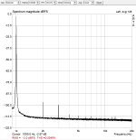
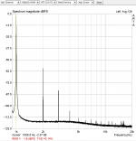
Real world tests have been done on the preamp. There is an additional knob besides the volume knob. It varies the harmonics between the two extremes shown in the attached pictures. Looks fun?
Real world tests have been done on the preamp. There is an additional knob besides the volume knob. It varies the harmonics between the two extremes shown in the attached pictures. Looks fun?
Attachments
Update:
Hi everyone.
I printed a batch of 40 boards of V4H Rev1. Interested members won't have to wait for GB list until this batch lasts.
Leave a post or send me a PM if you need a pair or more.
Thanks
Hello Shaan
One of the fellow members was in lot of praise for your design and recommended that I should build it. Before asking for pcbs can you kindly share the specs of this amp.
Regards
Vikram
Hello Shaan
One of the fellow members was in lot of praise for your design and recommended that I should build it. Before asking for pcbs can you kindly share the specs of this amp.
Regards
Vikram
Hi Vikram.
Specs are shared in post #1 of this thread. Link in my signature "v4h gb".
Hi Vikram.
Specs are shared in post #1 of this thread. Link in my signature "v4h gb".
Got it thanks.
Can this amp run on lower voltages say 24-0-24 v, I need about 150 watts @ 4 ohms. And 24v trafos are easily available near me.
Yes it can. But for 150w into 4ohm you will need 30-0-30 transformer.
I think the only way you will be able to do this is with a bridged pair of amps. This issue is not a comment on a specific model of amp.Can this amp run on lower voltages say 24-0-24 v, I need about 150 watts @ 4 ohms.
Yes it can. But for 150w into 4ohm you will need 30-0-30 transformer.
After rectification voltage will be higher, close to 33v. Will that work. 24-0-24v trafos are easily available. Will have to custom order for any other value which is very costly affair.
I can use 1 trafo per channel if needed.
After rectification voltage will be higher, close to 33v. Will that work. 24-0-24v trafos are easily available. Will have to custom order for any other value which is very costly affair.
I can use 1 trafo per channel if needed.

After rectification voltage will be higher, close to 33v. Will that work.
Missed the question, sorry.
Yes it will work definitely.
But if your target is 150W/4Ohm then a 24v transformer will not give you that power ceiling. It will be limited to around 100W or so.
Real world tests have been done on the preamp. There is an additional knob besides the volume knob. It varies the harmonics between the two extremes shown in the attached pictures. Looks fun?
Hi Shaan,
Could you please share more details about the preamp and additional harmonics knob..
Hi Shaan,
Could you please share more details about the preamp and additional harmonics knob..
Will do shortly. Thanks for your interest.
Missed the question, sorry.
Yes it will work definitely.
But if your target is 150W/4Ohm then a 24v transformer will not give you that power ceiling. It will be limited to around 100W or so.
In that case i will have to custom order the trafo.
Can you recommend trafo value for this amp and any suggestion where we can get good quality trafo at reasonable cost.
Also will any part values change according to lower voltage.
In that case i will have to custom order the trafo.
Can you recommend trafo value for this amp and any suggestion where we can get good quality trafo at reasonable cost.
Also will any part values change according to lower voltage.
30-0-30/300VA per channel. You can get them from torotrans.com
Only the 470R and 33k will need to be changed to 330R and 27k.
The price you have quoted 20USD, Is it for stereo pair or single mono pcb.
Single pcb.
I have been googling for quite some time now, I cant find any source for the power mosfets.
This is a most reliable source for the replacement parts:
Lateral MOSFETs from Exicon | Profusion Audio Design
- Home
- Group Buys
- PeeCeeBee V4H GB