Shaan,
Are you still able to supply the MOSFETS for this as in the previous Group Buy?
-Michael
Yes, of course.
After Shaan permission, We still have the SMPS-600 at discounted prices for this nice amplifier @ 55$ each.
Limited quantity available.
Awesome.

")
Shaan, might be pushing it, but what are your thoughts on running these boards at +/-65 Vdc? I recently acquired a 47x2 Vac 725VA toroidal and trying to decide if I should go with the V4H, or a Honey Badger from the DIYA store?
Is this a significant enough increase in voltage that it would cause problems? Thanks
Is this a significant enough increase in voltage that it would cause problems? Thanks
Thanks bambadoo...I don't plan to run it full power at any time, mainly just headroom.
It appears only 1 cap would need to go from 63V to 80-100V, and I was hoping a change from BC546 to 2N5550 or 2N5551 would be easy enough, at least according to the spec sheets. The KSE340 looks up to the job already.
It appears only 1 cap would need to go from 63V to 80-100V, and I was hoping a change from BC546 to 2N5550 or 2N5551 would be easy enough, at least according to the spec sheets. The KSE340 looks up to the job already.
Hi bullitstang.
As bambadoo said, the rating of the small trannies are the main limiting factor. Additionally, there is little to gain from a higher voltage than a little higher power with these MOSFETs with their high saturation voltage. If you need 300+ watts then I suggest you go for a different amp with BJT outputs which can actually take advantage of the higher rails more effectively.
As bambadoo said, the rating of the small trannies are the main limiting factor. Additionally, there is little to gain from a higher voltage than a little higher power with these MOSFETs with their high saturation voltage. If you need 300+ watts then I suggest you go for a different amp with BJT outputs which can actually take advantage of the higher rails more effectively.
I just completed the wiring and initial tests of my V4H with rev1 mods. I’m not one for words about my listening experiences, but I can say listening for a good portion of the day I did experience toe tapping and goosebumps! Out of the amps I’ve built, the V4H has the most power and the least amount of hum - none, even with my ear to the speaker. Thanks Shaan for sharing your talents and time to bring us this amp!
I have attached some pictures of my final build. I’ll detail below the supporting components for those interested.
- Schaffner FN9244B-10-06, 10A IEC filter, medical grade version
- TE W33 mains switch with built in circuit breaker, tripping at 5A.
- JLE softstart / delay: Amplifier Modules and PCBs For Sale. JLesterP is great to work with and his boards both cheap and great to build! I really like that they run off of their own transformer and not directly off of the mains. The small transformer with 120v primaries is direct from Zettler Home Page | ZETTLER MAGNETICS, INC..
- Dual mono Antek AS-3440 (AS-3440 - 300VA 40V Transformer - AnTek Products Corp) with their expensive - but very nice - steel transformer covers (CA-300 Steel Cover - AnTek Products Corp)
- Dual mono CRC PSUs from Prasi / Project16: CRC Power Supply (Class A amplifier). Secondary snubber measured using the Quasimodo. 2x UCC 63v/33000uF caps (https://www.mouser.com/ProductDetail/661-ESMH630T333MB80T) per channel per rail. CRC resistor is 0.5R, 10w Ohmite (https://www.digikey.com/product-detail/en/ohmite/40JR50E/40JR50E-ND/1124926). I need to replace the bleeder resistors as they run super hot. I forgot to recalculate them after moving to 56v rails and they are bleeding off 3.5w currently (1K0). Even though they are rated for 5w, I may bump them to 3K3 to lower the dissipation and heat.
- All of the rails run through fuses mounted on the rear panel. Currently fitted with 5A fast blow fuses and haven’t had any issues, except for when I shorted the speaker output and one of the fuses blew =) I need to measure the actual rail current under load and maybe fit in a smaller (4A?) slow blow fuse.
- V4Hs with the Rev1 mod, fitted with Exicons and CDE silver mica in place of ceramics. PRP 1/4w and 1w resistors from www.soniccraft.com, Noble metal plate power resistors from eBay (https://www.ebay.com/itm/152908729458). Q1,2 and Q9,10 matched.
- The hot stuff is mounted to a piece of 1/4” aluminum angle and then bolted to the heatsinks making up the side of the chassis. For the Exicons I used Wakefield CD-02-05 thermal pads (https://www.digikey.com/product-detail/en/wakefield-vette/CD-02-05-247/345-1545-ND/7070009).
- Dual mono speaker protect board also from JLE. Powered by the extra 15vac secondaries on the transformer.
- Binding posts are Propeller Posts from Madisound (https://www.madisoundspeakerstore.c...sts/propeller-post-16mm-tc-binding-post-pair/). Great build quality and mounting compared to my typical Chinese posts, but not crazy $$$ like Mundorf or others.
- RCAs are CMC 816-WU from gd-parts on eBay, connected with twisted pair 22awg and terminated using TE MTA 100.
- About 1,000 quick disconnect tabs and connectors =)
Phew.
The following is the detail of my ground scheme. This is always the hardest thing for me during builds, but the V4H was very straightforward and I think the dual mono PSU really helped make this cleaner. The guide that I used for this build was ESP’s http://sound.whsites.net/earthing.htm.
- Transformer static shields connected to chassis close to transformer
- IEC ground bolted to rear panel chassis using the mounting method described on ESP
- A ground loop breaker per channel as described by Figure 4 on ESP’s grounding article. The earth connection is connected to the same chassis ground bolt as the IEC.
- Each channel with the following connected directly to PSU star ground: Speaker return binding post, ground loop breaker, speaker protection ground, V4H ground (SGND and PGND tied together at PGND). Luckily the PSU had exactly 4 ground tabs!
Next up is to finish designing a front panel and handles for this beefy chassis. For what its worth, this chassis is definitely overkill and doesn’t even get close to warm. But, if nothing else, the size allowed me to get the transformers as far away from the signals as possible.
Hi,
Congratz,
I love your build, and you ZRT too
Yes, of course.
Great!
Are these matched pairs?
Please add 4 pairs to my boards.
Are these matched pairs?
I don't match them manually. But as some buyers have mentioned, they come fairly closely matched between N-N and P-P.
Check here: Post 208
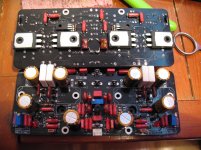
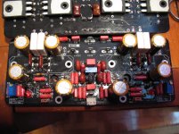
Last Friday I received the 100R replacement resistors, I managed to replace the 330r and 220R without damaging the PC boards.
I added the 6Pc silvered mica capacitors, I need to clean the PC boards (I do not want to use Acetone it will remove the solder mask finish and mess up the boards) and ready for power up. The 70% of alcohol I got does not work.
I think I will use some old heatsink I used for testing to power up and after I do some listening tests I will purchase a decent amplifier enclosure.
I see some people built some nice looking amp and based on the feedback this amp deserves a decent enclosure. Slowly I will get there.
Some parts are mounted at the bottom if you see missing from the top of the PC boards.
Attachments
- Home
- Group Buys
- PeeCeeBee V4H GB