Thanks Bao!
The Cresnet SMPS works very well paired with the V4H. Totally quiet entering/existing standby mode. I was relieved there was no “thump” or noises heard through the speakers.
I need more listening time to get a good impression about the V4H, I will say it seems to have a healthy amount of gain. My AKSA Lender preamp was set up for the MoFo and my head just about blew off with the volume knob at 25%
I lowered the Preamp’s gain, but I will try my B1 next.
Cheers
Vunce
Hi Shaan,
One V4 module - Stereo for me.. Enclosure and Transformer are available..as you know..
Waiting long time to get a class amplifier..
Regards,
Samrat
Will talk to you.
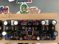
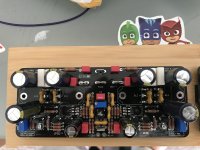
Finished populating the boards. Just need to put them in their destination and test
Attachments
-
 C135F2B2-9446-4FD2-8C42-85B4386932E4.jpg795 KB · Views: 481
 -
 4F43735B-2BB0-4B3E-9C2D-5E846F68C3FC.jpg758.9 KB · Views: 480
 -
 5AAE04D0-4BD4-4D04-85AD-2BE299DD3432.jpg884 KB · Views: 466
 -
 D2BA3A8F-8DB5-4A42-AC12-657507BF70B0.jpg1 MB · Views: 448
 -
 8AD29905-B383-4F14-ACA7-5E9E885258A7.jpg841.2 KB · Views: 438
Thanks Bao!
The Cresnet SMPS works very well paired with the V4H. Totally quiet entering/existing standby mode. I was relieved there was no “thump” or noises heard through the speakers.
I need more listening time to get a good impression about the V4H, I will say it seems to have a healthy amount of gain. My AKSA Lender preamp was set up for the MoFo and my head just about blew off with the volume knob at 25%
I lowered the Preamp’s gain, but I will try my B1 next.
Cheers
Vunce
Nice to hear that you are enjoying your amplifier paired with the 1200W SMPS.
thanks
I Like your enclosure, where did you get it??Finished populating the boards. Just need to put them in their destination and test
I'm happy to announce that the PeeCeeBee V4H has been updated to Revision 1.
Would you kindly update post #1?
TYVM!
Would you kindly update post #1?
TYVM!
Post 1 updated.
Another V4H is born!
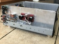
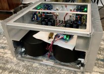
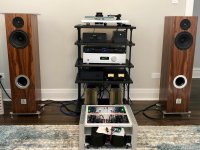
I just completed the wiring and initial tests of my V4H with rev1 mods. I’m not one for words about my listening experiences, but I can say listening for a good portion of the day I did experience toe tapping and goosebumps! Out of the amps I’ve built, the V4H has the most power and the least amount of hum - none, even with my ear to the speaker. Thanks Shaan for sharing your talents and time to bring us this amp!
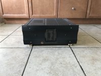
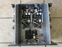
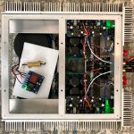
I have attached some pictures of my final build. I’ll detail below the supporting components for those interested.
- Schaffner FN9244B-10-06, 10A IEC filter, medical grade version
- TE W33 mains switch with built in circuit breaker, tripping at 5A.
- JLE softstart / delay: Amplifier Modules and PCBs For Sale. JLesterP is great to work with and his boards both cheap and great to build! I really like that they run off of their own transformer and not directly off of the mains. The small transformer with 120v primaries is direct from Zettler Home Page | ZETTLER MAGNETICS, INC..
- Dual mono Antek AS-3440 (AS-3440 - 300VA 40V Transformer - AnTek Products Corp) with their expensive - but very nice - steel transformer covers (CA-300 Steel Cover - AnTek Products Corp)
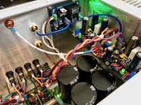
- Dual mono CRC PSUs from Prasi / Project16: CRC Power Supply (Class A amplifier). Secondary snubber measured using the Quasimodo. 2x UCC 63v/33000uF caps (https://www.mouser.com/ProductDetail/661-ESMH630T333MB80T) per channel per rail. CRC resistor is 0.5R, 10w Ohmite (https://www.digikey.com/product-detail/en/ohmite/40JR50E/40JR50E-ND/1124926). I need to replace the bleeder resistors as they run super hot. I forgot to recalculate them after moving to 56v rails and they are bleeding off 3.5w currently (1K0). Even though they are rated for 5w, I may bump them to 3K3 to lower the dissipation and heat.
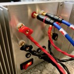
- All of the rails run through fuses mounted on the rear panel. Currently fitted with 5A fast blow fuses and haven’t had any issues, except for when I shorted the speaker output and one of the fuses blew =) I need to measure the actual rail current under load and maybe fit in a smaller (4A?) slow blow fuse.
- V4Hs with the Rev1 mod, fitted with Exicons and CDE silver mica in place of ceramics. PRP 1/4w and 1w resistors from www.soniccraft.com, Noble metal plate power resistors from eBay (https://www.ebay.com/itm/152908729458). Q1,2 and Q9,10 matched.
- The hot stuff is mounted to a piece of 1/4” aluminum angle and then bolted to the heatsinks making up the side of the chassis. For the Exicons I used Wakefield CD-02-05 thermal pads (https://www.digikey.com/product-detail/en/wakefield-vette/CD-02-05-247/345-1545-ND/7070009).
- Dual mono speaker protect board also from JLE. Powered by the extra 15vac secondaries on the transformer.
- Binding posts are Propeller Posts from Madisound (https://www.madisoundspeakerstore.c...sts/propeller-post-16mm-tc-binding-post-pair/). Great build quality and mounting compared to my typical Chinese posts, but not crazy $$$ like Mundorf or others.
- RCAs are CMC 816-WU from gd-parts on eBay, connected with twisted pair 22awg and terminated using TE MTA 100.
- About 1,000 quick disconnect tabs and connectors =)
Phew.
The following is the detail of my ground scheme. This is always the hardest thing for me during builds, but the V4H was very straightforward and I think the dual mono PSU really helped make this cleaner. The guide that I used for this build was ESP’s http://sound.whsites.net/earthing.htm.
- Transformer static shields connected to chassis close to transformer
- IEC ground bolted to rear panel chassis using the mounting method described on ESP
- A ground loop breaker per channel as described by Figure 4 on ESP’s grounding article. The earth connection is connected to the same chassis ground bolt as the IEC.
- Each channel with the following connected directly to PSU star ground: Speaker return binding post, ground loop breaker, speaker protection ground, V4H ground (SGND and PGND tied together at PGND). Luckily the PSU had exactly 4 ground tabs!
Next up is to finish designing a front panel and handles for this beefy chassis. For what its worth, this chassis is definitely overkill and doesn’t even get close to warm. But, if nothing else, the size allowed me to get the transformers as far away from the signals as possible.
I just completed the wiring and initial tests of my V4H with rev1 mods. I’m not one for words about my listening experiences, but I can say listening for a good portion of the day I did experience toe tapping and goosebumps! Out of the amps I’ve built, the V4H has the most power and the least amount of hum - none, even with my ear to the speaker. Thanks Shaan for sharing your talents and time to bring us this amp!
I have attached some pictures of my final build. I’ll detail below the supporting components for those interested.
- Schaffner FN9244B-10-06, 10A IEC filter, medical grade version
- TE W33 mains switch with built in circuit breaker, tripping at 5A.
- JLE softstart / delay: Amplifier Modules and PCBs For Sale. JLesterP is great to work with and his boards both cheap and great to build! I really like that they run off of their own transformer and not directly off of the mains. The small transformer with 120v primaries is direct from Zettler Home Page | ZETTLER MAGNETICS, INC..
- Dual mono Antek AS-3440 (AS-3440 - 300VA 40V Transformer - AnTek Products Corp) with their expensive - but very nice - steel transformer covers (CA-300 Steel Cover - AnTek Products Corp)
- Dual mono CRC PSUs from Prasi / Project16: CRC Power Supply (Class A amplifier). Secondary snubber measured using the Quasimodo. 2x UCC 63v/33000uF caps (https://www.mouser.com/ProductDetail/661-ESMH630T333MB80T) per channel per rail. CRC resistor is 0.5R, 10w Ohmite (https://www.digikey.com/product-detail/en/ohmite/40JR50E/40JR50E-ND/1124926). I need to replace the bleeder resistors as they run super hot. I forgot to recalculate them after moving to 56v rails and they are bleeding off 3.5w currently (1K0). Even though they are rated for 5w, I may bump them to 3K3 to lower the dissipation and heat.
- All of the rails run through fuses mounted on the rear panel. Currently fitted with 5A fast blow fuses and haven’t had any issues, except for when I shorted the speaker output and one of the fuses blew =) I need to measure the actual rail current under load and maybe fit in a smaller (4A?) slow blow fuse.
- V4Hs with the Rev1 mod, fitted with Exicons and CDE silver mica in place of ceramics. PRP 1/4w and 1w resistors from www.soniccraft.com, Noble metal plate power resistors from eBay (https://www.ebay.com/itm/152908729458). Q1,2 and Q9,10 matched.
- The hot stuff is mounted to a piece of 1/4” aluminum angle and then bolted to the heatsinks making up the side of the chassis. For the Exicons I used Wakefield CD-02-05 thermal pads (https://www.digikey.com/product-detail/en/wakefield-vette/CD-02-05-247/345-1545-ND/7070009).
- Dual mono speaker protect board also from JLE. Powered by the extra 15vac secondaries on the transformer.
- Binding posts are Propeller Posts from Madisound (https://www.madisoundspeakerstore.c...sts/propeller-post-16mm-tc-binding-post-pair/). Great build quality and mounting compared to my typical Chinese posts, but not crazy $$$ like Mundorf or others.
- RCAs are CMC 816-WU from gd-parts on eBay, connected with twisted pair 22awg and terminated using TE MTA 100.
- About 1,000 quick disconnect tabs and connectors =)
Phew.
The following is the detail of my ground scheme. This is always the hardest thing for me during builds, but the V4H was very straightforward and I think the dual mono PSU really helped make this cleaner. The guide that I used for this build was ESP’s http://sound.whsites.net/earthing.htm.
- Transformer static shields connected to chassis close to transformer
- IEC ground bolted to rear panel chassis using the mounting method described on ESP
- A ground loop breaker per channel as described by Figure 4 on ESP’s grounding article. The earth connection is connected to the same chassis ground bolt as the IEC.
- Each channel with the following connected directly to PSU star ground: Speaker return binding post, ground loop breaker, speaker protection ground, V4H ground (SGND and PGND tied together at PGND). Luckily the PSU had exactly 4 ground tabs!
Next up is to finish designing a front panel and handles for this beefy chassis. For what its worth, this chassis is definitely overkill and doesn’t even get close to warm. But, if nothing else, the size allowed me to get the transformers as far away from the signals as possible.
Attachments
- Home
- Group Buys
- PeeCeeBee V4H GB