That sounds like an improvement - thanks for all the hard work Shaan.
For the P channel Mosfets, are the gate resistors smaller than the N channel resistors?
Looking forward to the new schematic.
Gate resistors same for both N and P channel MOSFETs.
")
Happy New Year Shaan!
I still have 2 unmounted original V4H PCBs. Will it be possible to apply the new mods to those?
Cheers,
Jacques
Yes it will be possible.
V4H Rev1 Mod Tutorial
Hello PeeCeeBee V4H owners.
Here is how you can upgrade your boards with the Revision 1 Mod (shown for one channel).
Step 1:
Get 6 nos. 47pF/500V capacitors, ceramic or silver mica (12 nos. for two channels). These can be the same caps used for C5 and C6. Also get four 100ohm / 0.25W resistor for each channel.
Step 2:
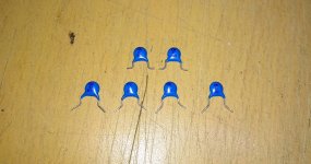
Bend their legs in the way shown in the picture below. Two of them bent at 90 deg and the rest bent at 45 deg, about 3mm far from their body.

Step 3:
Cut the legs as shown. Keep the 90 deg legs a little shorter and 45 deg legs a little longer.

Step 4:
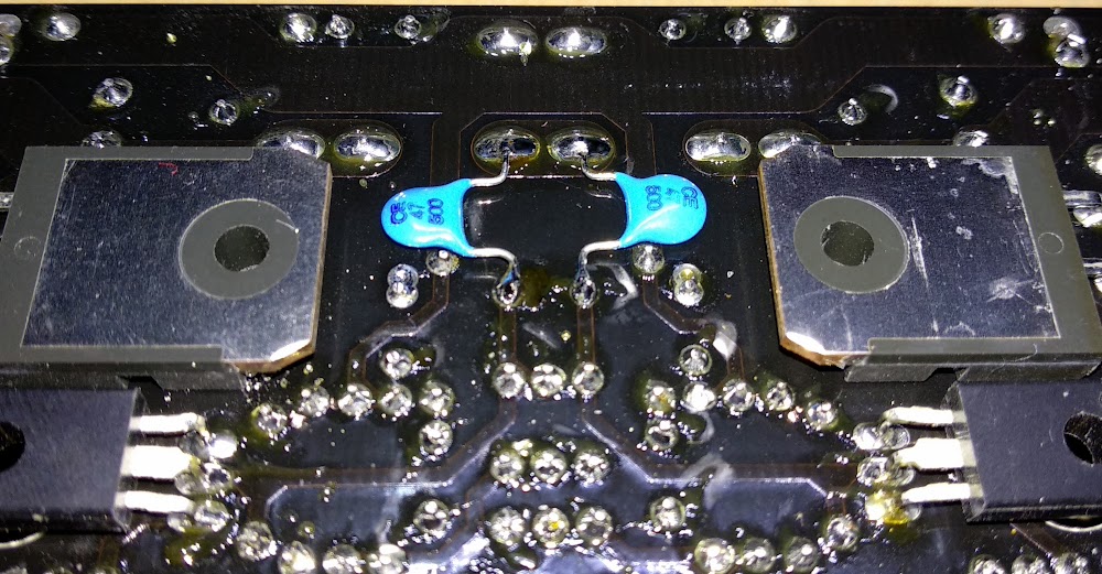
Take the two 90 deg bent capacitors and solder them on the bottom of the board as shown in the two pictures below. Solder one leg of each cap to a solder joint of the 1uF capacitor, and solder the other leg to the PGND solder joint. Make sure the capacitors lie flat so that when the board is mounted they don't touch the heatsink. Also take care so that thier legs don't touch any other solder joints.

Step 5:
Take the four 45 deg bent capacitors and solder each of them between pin 1 and 3 (gate and drain) of each MOSFET, as shown in the picture below.

Almost done.
Step 6:
Replace R27 through R30 with 100ohm resistors.
Step 7:
Mount the board on heatsink and set-up bias and offset following the guide shared in Post#1. If those were already set beforehand then no need to do it again, DC settings won't change after the mod.
Done.
____________________________
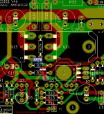
The Rev1 V4H layout looks like this. C23 through C28 added. Gate resistors will be changed in schematic, but places remain the same.

Thanks and
Hello PeeCeeBee V4H owners.
Here is how you can upgrade your boards with the Revision 1 Mod (shown for one channel).
Step 1:
Get 6 nos. 47pF/500V capacitors, ceramic or silver mica (12 nos. for two channels). These can be the same caps used for C5 and C6. Also get four 100ohm / 0.25W resistor for each channel.
Step 2:
Bend their legs in the way shown in the picture below. Two of them bent at 90 deg and the rest bent at 45 deg, about 3mm far from their body.
Step 3:
Cut the legs as shown. Keep the 90 deg legs a little shorter and 45 deg legs a little longer.
Step 4:
Take the two 90 deg bent capacitors and solder them on the bottom of the board as shown in the two pictures below. Solder one leg of each cap to a solder joint of the 1uF capacitor, and solder the other leg to the PGND solder joint. Make sure the capacitors lie flat so that when the board is mounted they don't touch the heatsink. Also take care so that thier legs don't touch any other solder joints.
Step 5:
Take the four 45 deg bent capacitors and solder each of them between pin 1 and 3 (gate and drain) of each MOSFET, as shown in the picture below.
Almost done.
Step 6:
Replace R27 through R30 with 100ohm resistors.
Step 7:
Mount the board on heatsink and set-up bias and offset following the guide shared in Post#1. If those were already set beforehand then no need to do it again, DC settings won't change after the mod.
Done.
____________________________
The Rev1 V4H layout looks like this. C23 through C28 added. Gate resistors will be changed in schematic, but places remain the same.
Thanks and

I chose EXICON mosfets (all do I had the Hitachi also) for my application if I understand well that would work well without oscillation.
Shaan please let me know, my PC boards NOT mounted on a heatsink yet.
Thank you!
In case I must do these mods.
I have to order the recommended parts from Partsconnexion from where I ordered the rest of the parts
I do hate desoldering- I use silver solder, for the second time does not want to melt and it can destroy the PC boards
VAS ground caps, the same as the ones soldered under the board. I took this picture while experimenting.
I chose EXICON mosfets (all do I had the Hitachi also) for my application if I understand well that would work well without oscillation.
Shaan please let me know, my PC boards NOT mounted on a heatsink yet.
Thank you!
In case I must do these mods.
I have to order the recommended parts from Partsconnexion from where I ordered the rest of the parts
I do hate desoldering- I use silver solder, for the second time does not want to melt and it can destroy the PC boards
You don't need to desolder anything. If you use the mod then place 150ohm in parallel with 330ohm gate resistors and 220ohm with the 220ohm gate resistors.
In step 4 how can i solder two caps on the top side of the board ?
Between VAS collectors and Q3/4 collectors, might be trickier and messier. Underside is recommended.
Is it possible to update this information i post#1?
Always great to have gathered all good information in first post.
Will do shortly.
ok thanks for the quick reply.VAS ground caps, the same as the ones soldered under the board. I took this picture while experimenting.
I also used the WBT 0820 silver solder. I was also worried about to desoldering but it was fairly easy to desolder.I do hate desoldering- I use silver solder, for the second time does not want to melt and it can destroy the PC boards

Between VAS collectors and Q3/4 collectors, might be trickier and messier. Underside is recommended.
Hi Shaan, For step 4 on top pcb side, I checked the PCB , can i do this modify like this image?
Will do shortly.
Attachments
Last edited:
Great work shaan! Just in time for my parts order at mouser.
Is there any sonic benefit by using silver mica for any of the caps in the new rev?
Ceramic and Silver Mica have been suggested for best HF performance. In audible frequencies there is no effect for either type.
Hi CK.
Yes you can but the green traces are on bottom layer.
Ok . then i re-route the connection to the red trace at C11 minus contact

- Home
- Group Buys
- PeeCeeBee V4H GB