Components
JMK,
you can also use the Vishay CMF55 1/2 watt series.
Dimensions below and these are usually 50ppm.
Diameter: 2.29 mm
Length: 6.1 mm.
Like the RN55 series, they are not attracted to magnets and are of better quality than the cheap 0.5/ 0.6 Watt Chinese resistors.
Kheon,
I assume that you know that the KSC3503DS has a different gain to the KSA1381ESTU? Not sure if that matters.....
Yes but didn't found both D or both E, one is 60 - 120 the other is 100 - 200, if i'm lucky i'll find 2 pairs around 110

If not, i'll put KSE340 /KSE350
Hi guys, just a small question does anybody know a good source of heatsinks, preferably a cheaper one that cuts to size? Also I just managed today to screw up one board a little, I swapped C17 with the 2200uF, what a headache to fix the mistake, just to make things short I lifted the pad from the bottom and had to solder C17 just using the through-hole surface, I have a good connection and seams good mechanically, it should be fine . I learned without wanting that for thick PCB's with plated holes you must be very careful , even with decent tools I can be tricky to clear the hole, eventually i had to use a small pin to stick it inside...pfff ) .
So if someone know a good source of heat-sinks please let me know and others reading these posts in the same time.
) .So if someone know a good source of heat-sinks please let me know and others reading these posts in the same time.
So if someone know a good source of heat-sinks please let me know and others reading these posts in the same time.
You could try:
https://www.heatsinkusa.com/?url=ht...MI2uLn-ba03gIVEQ8YCh302AO0EAAYAiAAEgK5lfD_BwE
Hi guys, just a small question does anybody know a good source of heatsinks, preferably a cheaper one that cuts to size? Also I just managed today to screw up one board a little, I swapped C17 with the 2200uF, what a headache to fix the mistake, just to make things short I lifted the pad from the bottom and had to solder C17 just using the through-hole surface, I have a good connection and seams good mechanically, it should be fine . I learned without wanting that for thick PCB's with plated holes you must be very careful , even with decent tools I can be tricky to clear the hole, eventually i had to use a small pin to stick it inside...pfff
So if someone know a good source of heat-sinks please let me know and others reading these posts in the same time.
hifi200.it , on their spare parts page, has good rectangular black heatsinks, if you're located in Europe.
Jmk
Hi guys,
So if someone know a good source of heat-sinks please let me know and others reading these posts in the same time.
Sorry, you have to go on their business page, here:
Dissipatori
Jmk
Shann, wouldn`t be more logical to connect speaker GND to PGND on amplifier board and then take a wire from this point to the star ground point of the chassis? The paths are quite shorter and minimized compared to your recommendation - connecting speaker GND to star ground...I am using dual secondaries PSU each / channel.
Shann, wouldn`t be more logical to connect speaker GND to PGND on amplifier board and then take a wire from this point to the star ground point of the chassis? The paths are quite shorter and minimized compared to your recommendation - connecting speaker GND to star ground...I am using dual secondaries PSU each / channel.
Hi Andrej.
The speaker return carries the total speaker current, and it has only one destination - the source i.e. the capacitor bank.
If we route the speaker return to PGND on amplifier board, then the wire that connects PGND to PSU ground will carry the speaker return current to the capacitor bank from where it was taken by the MOSFETs. Since this wire has some (very small) resistance, the speaker return current flowing through it will cause a voltage to develop across it, and the amplifier will directly see this voltage in its 0V node, exactly where it should Not be. In other words we now have a dirty ground connected to the amplifier and this is not a good idea if the amplifier is expected to perform at its best.
I recommend routing the speaker return directly to PSU's 0V point, not anywhere else. This ensures that speaker return and amplfiier's PGND node are now connected to 0V via different conductors. As a result no unwanted voltage is generated in the conductor that connects PGND and PSU's 0V, and the amp now sees a clean ground.
Cheers.
Thank you for explanation. Do you suggest connecting both (left and right channel) PSU`s 0V point to the main central ground point, where mains earth is connected to the chassis or rather leave it floating?
Thank you for explanation. Do you suggest connecting both (left and right channel) PSU`s 0V point to the main central ground point, where mains earth is connected to the chassis or rather leave it floating?
Having chassis and heatsinks at PSU's 0V potential is more important than having them at mains earth potential for most stable operation of the amplifiers.
You can connect both 0V to chassis central mains earth ground via two ground loop breakers, one for each PSU.
My PSU(dual) ground is lifted with 10 ohm resistor. My heatsinks are grounded through main earth. I have a constant slight hum/noise which is not amplified. 
Might be my DC protect circuit, which i added after trying fake mosfets...
Is ground loop breakers safe - how should they be designed? Guess it ought to handle quite a bit current in case of a fault?
Might be my DC protect circuit, which i added after trying fake mosfets...
Is ground loop breakers safe - how should they be designed? Guess it ought to handle quite a bit current in case of a fault?
Attachments
You can connect both 0V to chassis central mains earth ground via two ground loop breakers, one for each PSU.
Thanks for noting this, I intend to use ESP’s ground loop breaking circuit as described at Earthing (Grounding) Your Hi-Fi - Tricks and Techniques. One per mono PSU for each channel.
Greg
My PSU(dual) ground is lifted with 10 ohm resistor. My heatsinks are grounded through main earth. I have a constant slight hum/noise which is not amplified.
Might be my DC protect circuit, which i added after trying fake mosfets...
Is ground loop breakers safe - how should they be designed? Guess it ought to handle quite a bit current in case of a fault?
Hi,
which power resistors did you use and do you have any problem with them? Are they magnetic?
Thx,
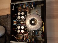
My PSU(dual) ground is lifted with 10 ohm resistor. My heatsinks are grounded through main earth. I have a constant slight hum/noise which is not amplified.
Might be my DC protect circuit, which i added after trying fake mosfets...
Is ground loop breakers safe - how should they be designed? Guess it ought to handle quite a bit current in case of a fault?
Hi Medisinmannen,
have you got separate grounds for left and right on your speaker protection board? If not, disconnect the board and run the output cables directly from the PCB to the speaker posts. See if that makes a difference.
I noticed that your speaker cables from the pcb run right next to the transformer. You might want to relocate the two cables away from the transformer.
See ground loop breakers here:
Earthing (Grounding) Your Hi-Fi - Tricks and Techniques
Power Supply for Power Amplifiers
My PSU(dual) ground is lifted with 10 ohm resistor. My heatsinks are grounded through main earth. I have a constant slight hum/noise which is not amplified.
It looks like you connected the grounds from both PSU directly to the chassis metal without any loop breaker. This may have caused the noise. It being not amplified is another indication that you have ground loops.
Might be my DC protect circuit, which i added after trying fake mosfets...
I don't think it is the DC protection circuit that is causing the problem.
Is ground loop breakers safe - how should they be designed? Guess it ought to handle quite a bit current in case of a fault?
Yes they are safe. You need the following components to build one.
One 35A bridge rectifier module (KBPC3510 type)
One 100nF/100V capacitor
One 10R/2W resistor
Short the two AC inputs of the bridge rectifier with thick wire soldered to the tags.
Short the + and - outputs of the bridge the same way.
Connect 100nF between the shorted AC and shorted DC tags.
Connect the 10R resistor the same way, in parallel to the capacitor. The loop breaker is ready.
Connect the shorted AC to PSU ground. Connect the shorted DC to chassis metal.
Connect mains earth directly to chassis metal.
For two PSUs you will need two loop breakers.
I hope this helps.
Thanks for noting this, I intend to use ESP’s ground loop breaking circuit as described at Earthing (Grounding) Your Hi-Fi - Tricks and Techniques. One per mono PSU for each channel.
Greg

Hi
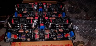
I got my v4h boards and the parts a while back. I have now started to put in the components together. I accidentally touched the soldering Iron to one of the 100nf 100v cap. should I replace it?
(And if you are wondering about those nuts and bolts, they are their to align the mosfets to the holes on board)
Thanks
Bharat Singh
Attachments
My PSU(dual) ground is lifted with 10 ohm resistor. My heatsinks are grounded through main earth. I have a constant slight hum/noise which is not amplified.
Might be my DC protect circuit, which i added after trying fake mosfets...
Is ground loop breakers safe - how should they be designed? Guess it ought to handle quite a bit current in case of a fault?
Hi,
which power resistors (0.1R 5W) you choose for this amp? Can you give order code'
Thanks,
- Home
- Group Buys
- PeeCeeBee V4H GB