Heat & capacitors
My concern was aimed at capacitors life's lasting.
A few degrees less for the pcb wouldn't hurt in my opinion ......
JMK
Hi JMK.
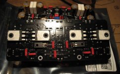
No need. Fix the board flat on mosfets' face.
My concern was aimed at capacitors life's lasting.
A few degrees less for the pcb wouldn't hurt in my opinion ......
JMK
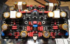
Just finished the PC boards stuffing.
Yes, you right the Acetone made my boards messy. I have to buy some alcohol to clean them nicely.
Do you think 99% rubbing type of alcohol will work? Homebrew type of PC board and factory type like TV had no issue to clean it with acetone.
I choose EXICON power mosfets instead of Hitachi.
Yes, you right the Acetone made my boards messy. I have to buy some alcohol to clean them nicely.
Do you think 99% rubbing type of alcohol will work? Homebrew type of PC board and factory type like TV had no issue to clean it with acetone.
I choose EXICON power mosfets instead of Hitachi.
Attachments
0R1 resistors
Here in EU ,I use Kontact WL to clean everything and cotton sticks for smoking pipes that are very cheap.
My answer these 0R1 5W resistors that are touching the capacitors have to be non inductive ? Have ordered one 605-RWHSE09TQ000R1FS at Mouser to look at,it's very reduced and fit the board . 0,06 uh at 100kz
These resistors don't have to be non-inductive thanks to the two zobel networks. If you look closely the zobels are not taken right from output, but from the joint of the two resistors in each side. This was done so that inductive resistors can be used without any problem.
Hi Shaan, is the schematic correct? I am asking because i noticed thar the 2sk 2sj are driven through a resistor, one side with 220 ohms and the other side with 330 ohms. Is that correct? Will the two resistors of 10 ohm supplying the low signal side get hot enough for just 600mW? Granted there shouldnt be much current needed.
Hi Shaan, is the schematic correct? I am asking because i noticed thar the 2sk 2sj are driven through a resistor, one side with 220 ohms and the other side with 330 ohms. Is that correct?
Yes those values are correct.
Will the two resistors of 10 ohm supplying the low signal side get hot enough for just 600mW? Granted there shouldnt be much current needed.
Even with 250mW resistors we need about 150mA current to burn them. Now, current through input+VAS is around 15mA. So it's fine.
(sorry for late reply
)
Resistors ratings
Hi !
I'm into checking my BOM (the one that's been posted page 19 post #187)
I notice that most resistors are 400mW on that BOM, when according to what you (Shaan) say 250mW are more than enough.
Beside this, it looks like 400mW will be quite difficult to fit on the pcb in several places.
Could you please confirm which should actually be more than 1/4 watt ?
There is a full list of the required components on page 2 of you setup documentation, but I feel that more details on their necessary ratings would be helpful !
Thanks a lot
JMK
Hi JMK.
These should be 1/4W resistors i.e. 250mW and not 400mW, as mentioned in BOM I posted in Post 74 which is also linked in Post 1.
Hi JMK.
These should be 1/4W resistors i.e. 250mW and not 400mW, as mentioned in BOM I posted in Post 74 which is also linked in Post 1.
OK, this other 'updated' BOM is confusing.
All 250mW - NO EXCEPTION
Thanks a lot
JMK
All 250mW...
Post74?
Well, all of them are, "Unless Otherwise Specified."
Post74?
Well, all of them are, "Unless Otherwise Specified."
Of course, thanks for reminding !
JMK
https://www.diyaudio.com/forums/group-buys/317151-peeceebee-v4h-gb-46.html#post5545688
Take a look at 456 .
Resistors should not be longer than 8 mm and the diameter should not be bigger than 2.5mm to fit the proper way.
Some resistors will have a rated power of 0.250w(ex: RN60 series) but their sizes will be way bigger than what we need here , some resistors rated 1w(ex: cpf1 series) are perfect in
size .
Hi
If it's useful I'll share my BOM on Mouser :
Mouser Electronics, Inc. France
Just chage the qantity of the BC546/556 and change the KSC3503 and KSA1381 with the right one (I wanted to test with these)
Fabio
If it's useful I'll share my BOM on Mouser :
Mouser Electronics, Inc. France
Just chage the qantity of the BC546/556 and change the KSC3503 and KSA1381 with the right one (I wanted to test with these)
Fabio
Hi
If it's useful I'll share my BOM on Mouser :
Mouser Electronics, Inc. France
Just chage the qantity of the BC546/556 and change the KSC3503 and KSA1381 with the right one (I wanted to test with these)
Fabio
You're into 1/8 watt resistors !!
JMK
You're into 1/8 watt resistors !!
JMK
No, that's because the Rn55d are the military version. Equivalent to the normal 1/4w version which are CMF55
- Home
- Group Buys
- PeeCeeBee V4H GB