Hello shaan and other V4H builders,
I am about to attempt Rev1 and Rev2 mods to my original V4H boards. I will start off with the mods before installing any other components that are not necessary to the mods. I am proposing to start with Rev2 mod which involves the trace cutting. Rev1 mods I should be able to handle.
Are there any tips to perform cutting a trace, like how much pressure , how deep to cut, does it have to be a certain distance wide or just a blade width with a sharp knife. Any tips would be welcome, as I have never attempted this before.
Thanks for the help,
MM
Myles,
If you have one available, I have a Dremel tool that I use, so I can be extremely accurate in my cutting of traces. Basically you are removing a small portion of the silkscreen and then removing the underlying copper connection. You can do this a little bit at a time.
After that, I test to see if there is still a connection or not with my DMM.
Just my $0.02 worth.
Best,
Anand.
P.S. Practice on a cheap disposable pcb first, then go attacking your precious V4H board!
OK, traces are cut and no continuity between - lead of C11 and pin3 of Q3 (if reading from top of pcb) and pin 3 of Q4 (if reading from top of pcb) and +lead of C12.
Are these the points where the 4K7 R39 and R40 are soldered to the leads of the caps and the transistor leads.
Also are the resistors soldered on the bottom or top of pcb.
Just want to check before proceeding.")
Are these the points where the 4K7 R39 and R40 are soldered to the leads of the caps and the transistor leads.
Also are the resistors soldered on the bottom or top of pcb.
Just want to check before proceeding.
Last edited:
OK, traces are cut and no continuity between - lead of C11 and pin3 of Q3 (if reading from top of pcb) and pin 3 of Q4 (if reading from top of pcb) and +lead of C12.
These are pin 1, the collectors of q3 and q4, reading with the flat sides of the bjts facing you.
Are these the points where the 4K7 R39 and R40 are soldered to the leads of the caps and the transistor leads.
Yes.
Also are the resistors soldered on the bottom or top of pcb.
Bottom.
Hi shaan and other builders,
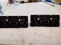
See pics of R39/R40 and trace cuts. Next up I was planning to solder in the MFets Q11,12,13,14, and continue with Rev2 mod and Rev1 mod.
Question: Is it a good idea to "try and solder" the short circuit protection (IN4148/10V zener) and the 47pf cap at the gate of the Mfet and solder all 3 pieces in one solder application, or is better to solder MFets first and then reheat the solder joint and add the other components. I was planning to do in 2 steps, Mfets first and then the caps and short circuit in step two. Seems safer and less prone to failure for a builder with my skills.
Also, does there need to be breather space between the Mfet and the pcb for heat dissipation/ventilation?
Thanks for the help,
MM
Attachments
V4H upgraded to REV.2


The V4H PCB is shown from the top in picture #1, picture #2 shows the back of the PCB.
Picture #3 is a close-up of the diodes (1N4148/zener diode) and capacitor (47pF) mounted around the MOSFETs,
and picture #4 shows the resistor (4k7) mounted on the back of the PCB.
Maybe this will give you an idea of how to do the upgrade 😊
Updated text for V4H Rev.2:
The V4H PCB is shown from the top in picture 1, picture 2 shows the back of the PCB.
Image 3 is a close-up of the diodes (1N4148/zener diode) and capacitor (47pF) mounted around the MOSFETs, and image 4 shows the resistor (4k7) mounted on the back of the PCB between Q3/Q4 collector and ground (C11-/C12+ ).
Then there are decoupling capacitors C23/C24 of 47pF mounted between Q9/Q10 collector and ground,
ref see drawing for V4H Rev.2. Also picture #2.
Maybe this will give you an idea of how to do the upgrade 😊
/Helge
Thanks for the pics Torv. Only question I have is: "did you solder the 47pf caps on the Mfets first" before adding the 1N4148/ zener network, or do it all in one shot. My 4K7 resistor is a bit different looking than yours, but accomplishes the same thing I think.
Cheers
Cheers
Thanks Torvbakkane and shaan,
I have found that I can stuff both the diodes and the Mfets into the pad holes, so should only have to apply heat once to the solder in place.
shaan, looks like I will have to order some 10V 1W zeners. Lot's of other stuff to solder in place while waiting.
Thanks
I have found that I can stuff both the diodes and the Mfets into the pad holes, so should only have to apply heat once to the solder in place.
shaan, looks like I will have to order some 10V 1W zeners. Lot's of other stuff to solder in place while waiting.
Thanks
Hi shaan,
I finished off Rev1 and Rev 2 mods on one of the V4H boards. See pics. I wanted to do a continuity test on the MFets to see if OK.
On Mfet q13,q11, red probe on D, black probe on S gives continuity
On Mfet q12, q14, red probe on S, black probe on D gives continuity
Everything operating as it should be ?
Thanks
The Q9 and Q10 that I am using are fully plastic bodies. Is it absolutely necessary to mount them on the heat sinks?.
If so I will have to de-solder as I have mounted on the top of board. Not a problem to de-solder, just a error on my part.
I do have some metal backed Q9 and Q10, so is it better to mount these on the heatsink rather than the
plastic body ones.
Thanks for the help.
If so I will have to de-solder as I have mounted on the top of board. Not a problem to de-solder, just a error on my part.
I do have some metal backed Q9 and Q10, so is it better to mount these on the heatsink rather than the
plastic body ones.
Thanks for the help.
Yes, Q9 and Q10 need to mount to the heatsink and the preferred location is underneath the board and close to the outputs. They provide the bias tracking and without them mounted on the heatsink you could run the risk of the over biasing the outputs and they could self-destruct. You could try and mount them on the heatsink via flying leads if you can't mount them in the designers location under the board, but again this would/could be sub-par, because the preferred spot is close to the outputs for temperature tracking.
There's no difference in performance in plastic and metal backed - only that the metal backed must have an insulator between them on the heatsink, or you will have a dead-short with the heatsink.
There's no difference in performance in plastic and metal backed - only that the metal backed must have an insulator between them on the heatsink, or you will have a dead-short with the heatsink.
- Home
- Group Buys
- PeeCeeBee V4H GB