https://www.diyaudio.com/forums/members/shaan.html
i want to buy 4 pcb. Is this product available anymore?
Yes. Available.
")
IT's ALIVE & singing sweetly. Board 2 next. Thanks Shaan
Happy to know!


Hello,
please HELP
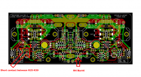
When setting VAS biasing, I was carelessly manipulating the multimeter probe and a short time I connected the legs R25 and R39.
It sparkled a bit and the R4 resistor burned out before I turned off the power on. Shown in the picture below.
What was destroyed? Transistor? Who?
I'm not an expert to find a mistake. I can only measure components if I know which ones.
I hope this is a small problem and I can repair it.
Thank you for the advice.
please HELP
When setting VAS biasing, I was carelessly manipulating the multimeter probe and a short time I connected the legs R25 and R39.
It sparkled a bit and the R4 resistor burned out before I turned off the power on. Shown in the picture below.
What was destroyed? Transistor? Who?
I'm not an expert to find a mistake. I can only measure components if I know which ones.
I hope this is a small problem and I can repair it.
Thank you for the advice.
Attachments
Ola Shaan. Eu gostaria de adquirir 2 pcb's do V4H. Como proceder? Obrigado.
Translation said:Hello Shaan. I would like to purchase 2 pcb's from V4H. How to proceed? Thanks.
 Por favor, note que este é um fórum em inglês
Ola Shaan. Eu gostaria de adquirir 2 pcb's do V4H. Como proceder? Obrigado.
Hi Alstarnet. Yes, PCBs are available. You will have PM shortly.
Hello,
please HELP
When setting VAS biasing, I was carelessly manipulating the multimeter probe and a short time I connected the legs R25 and R39.
It sparkled a bit and the R4 resistor burned out before I turned off the power on. Shown in the picture below.
What was destroyed? Transistor? Who?
I'm not an expert to find a mistake. I can only measure components if I know which ones.
I hope this is a small problem and I can repair it.
Thank you for the advice.
Hi Robodo.
Check all the resistors. Replace the burnt ones.
Check all bipolars for base-emitter and base-collector voltage with multimeter in diode test mode. For Q1,3,5,7,9 black probe goes to base, for Q2,4,6,8,10 black probe goes to base. Pin 2 is base for small bipolars and pin 1 is base for Q9/Q10. If any junction shows open or short, replace that transistor. Remove jumpers before probing.
Hello Shaan,Only hFE needs to be matched. Q1/Q2 and Q9/Q10, correct.
I was able to match q1 and q2 perfect but on q9/q10 i m having trouble.
On a batch 30 mje340 and 30 350 i have no 340 higher than 80 hfe and 350 no lower than 119hfe.
Should i buy more? what is the max diference alowed?
Sorry for this question but i m learning.
Thks.
Thks... for the help. I will need to buy more to get the right ones....Hi Pistollero.
A difference of upto 25% is fine. See if you can get 340 with 100 or more hFE.
No need to say sorry for asking questions.
Bests.
[emoji106][emoji846]
Hi Robodo.
Check all the resistors. Replace the burnt ones.
Check all bipolars for base-emitter and base-collector voltage with multimeter in diode test mode. For Q1,3,5,7,9 black probe goes to base, for Q2,4,6,8,10 black probe goes to base. Pin 2 is base for small bipolars and pin 1 is base for Q9/Q10. If any junction shows open or short, replace that transistor. Remove jumpers before probing.
Hi shaan,
Thank you for your help. I measured all the resistors and replaced only the burned R4, the others were fine. Then I measured the transistors and I detected faulty Q2
First I also desoldered the Q4, Q8 and Q10 because I thought they were also defective,...
...before I found out that for NPN transistors it is necessary to apply a red probe goes to base and then these transistors were already good.shaan said:...for Q2,4,6,8,10 black probe goes to base
So I soldered them back. I'm glad I have more of these transistors, because I destroyed the desoldered ones.
After attaching the finished board to the heatsink and connecting the power supply. Everything seems to be fine.
Tomorrow I will make setup VAS, Offset and more, I'm finishing today.
I don't like two differences. It just seems to me that the LED D6 versus D5 is a little dimmer. And resistance between the output terminal and heatsink body is 4,7 MOhm.
This does not happen with the second PCB module. I already have it installed and all setup fine.
Any advice? Thank you.
Robert
I don't like two differences. It just seems to me that the LED D6 versus D5 is a little dimmer. And resistance between the output terminal and heatsink body is 4,7 MOhm.
This does not happen with the second PCB module. I already have it installed and all setup fine.
Replace the led that's dim.
If it's showing 4.7Mohm without heatsink connected to psu ground then somewhere there is a slight leakage between mosfet backs and heatsinks. Replace the insulators.
Hi shaan,
the resistance between ground and output is ok. I measured it with the power supply connected
Today I tried to set the VAS, but the mV value didn't want to change, still 0mV, even though I was rotating VR1 and VR2. As the VR2 rotates, LED D6 dims to completely dark. If I turned the trimmer back to the maximum resistance, then is the light back on D6
I'm finishing today, I won't continue until after the weekend. I should give time to my family
Robert

Tks Vunce[emoji106][emoji106][emoji106][emoji6]Hahaha!! That’s the way Pistollero
Excellent progress on Shaan’s fine V4H
Last edited:
- Home
- Group Buys
- PeeCeeBee V4H GB