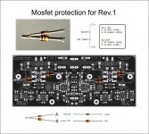
Here is a basic short circuit protection for the MOSFETs that will be implemented in the next revision of PCBs, shown in first attachment. You can install it right between the gate and source pins (pin 1 and pin 2) of each mosfet. Four networks needed per channel. You can easily make them the way shown in the second attachment. The diodes can stand vertically or lie down horizontally as per your convenience.
For Q11 and Q13, anode of 4148 (marked "A") goes to gate (pin1), and anode of zener (marked "B") goes to source (pin2). For Q12 and Q14, anode of 4148 goes to source (pin2), and anode of zener goes to gate (pin1). Cathodes of the two diodes are joined together in each network. Total diodes needed - 1N4148 x8 and 10V zener x8 for two channels. Typically half the number of diodes are used, but this way we bypass the gate resistors and have the protection right at individual mosfet gates.
It is not essential for normal operation of the amp but will save the mosfets in case of a short at the output happens.
Bests.
I have made a visual install guide for rev1 boards MOSFET protection diodes that Shaan published the other day

Attachments
I have made a visual install guide for rev1 boards MOSFET protection diodes that Shaan published the other day
OK, thanks a lot ........... but I have a question :
What actually happens in case a short on output actually happens - and lasts for some time before you realize what just happened (beside no sound in the speaker if connected) ?
JM,
In that case a high current will keep flowing through the mosfets heating the heatsink as hell, until the power supply rail fuses or the mosfets blow due to overheat. Hence power supply output rail fuses should not be more than 10A rated for a couple V4H channels.
This protection is in a sense basic, i.e. not elaborate ones like VI limiters which directly monitor output current. In the sustained fault condition stated above BJT output devices will commit suicide in seconds, and zener protection is useless for BJT output - VI limiting is must. In contrast, lateral's very high on resistance and very high Vgs to Id ratio (low transconductance) means it will not go into secondary breakdown like BJTs when a short sustains, and the Vgs value for 5A+ drain current is sufficiently high that we can use zener diodes to limit Vgs (hence Id) to a safe limit until other forms of failsafe mechanism triggers i.e. fuses blow, or power is turned off.
 Thanks
In that case a high current will keep flowing through the mosfets heating the heatsink as hell, until the power supply rail fuses or the mosfets blow due to overheat. Hence power supply output rail fuses should not be more than 10A rated for a couple V4H channels.
This protection is in a sense basic, i.e. not elaborate ones like VI limiters which directly monitor output current. In the sustained fault condition stated above BJT output devices will commit suicide in seconds, and zener protection is useless for BJT output - VI limiting is must. In contrast, lateral's very high on resistance and very high Vgs to Id ratio (low transconductance) means it will not go into secondary breakdown like BJTs when a short sustains, and the Vgs value for 5A+ drain current is sufficiently high that we can use zener diodes to limit Vgs (hence Id) to a safe limit until other forms of failsafe mechanism triggers i.e. fuses blow, or power is turned off.
So with those protection in place it seems to me it would be a good idea to install temperature protection sensors that I have on softstart?
Just managed to power up one channel and perform those settings as per Shaan's manual.
I let it idle@215mV across the rail's 1R for half hour.
Heatsink temp is 46degC, is my heatsink size adequate for this design?
Conrad's 300x100x40
Thanks
Yes 300x100 is perfect.
So with those protection in place it seems to me it would be a good idea to install temperature protection sensors that I have on softstart?
With or without, a good idea to use thermal protection if available.
If I use a disc-type 10A 250V thermal switch fixed to the heatsink, what temperature rating would you recommend for the switch? Will 60 deg C be good?With or without, a good idea to use thermal protection if available.
Also, do you feel it's a good idea to route 250V through the switch? I was thinking of wiring the primary-side of the main power transformer through the switch. Is it better to wire the switch on the secondary side instead?
Hi tcpip.
I have no experience with these thermal switches so can't comment. You may want to follow the best practices.
I use the ESP thermo-fan controller Project 42 that is set to trigger the relay at a temperature too hot to keep my hands on heatsink for more than 5 seconds, set by VR1 in the circuit.
I have no experience with these thermal switches so can't comment. You may want to follow the best practices.
I use the ESP thermo-fan controller Project 42 that is set to trigger the relay at a temperature too hot to keep my hands on heatsink for more than 5 seconds, set by VR1 in the circuit.
Ok, thanks. I was referring to items like this: Buy MULTICOMP Thermal Switch, Low Profile, T23 Series, 100 �C, Normally Closed, Flange Mount in India from Tanotis online store at wholesale pricesHi tcpip.
I have no experience with these thermal switches so can't comment. You may want to follow the best practices.
I use the ESP thermo-fan controller Project 42 that is set to trigger the relay at a temperature too hot to keep my hands on heatsink for more than 5 seconds, set by VR1 in the circuit.
Lots of companies make similar items, I believe, including Cantherm and NTE. I first learned about them from Randy Slone 15 years ago; he used to use them in all his amps.
Hi Shaan, I've replaced defective pair of N mosfets with new ones and when powered up the amp the leds did not light up, after some component testing with the DMM I found out that R23/R24 had gone open, with new resistors in place the leds are on but I get a reading of 0mV when connecting the probes of the DMM to the legs of either R25 or R26.
One more thing, during powering up the amp one of the leds on the other channel board (the one that did not have any defects up to now) did not light up, after testing with the DMM I found out that R24 had gone open, any idea why R23/R24 are prone to defects? Could it be the type of used resistors? I've used Royal Ohm extra small size MF 40-SS 0.4W resistors.
One more thing, during powering up the amp one of the leds on the other channel board (the one that did not have any defects up to now) did not light up, after testing with the DMM I found out that R24 had gone open, any idea why R23/R24 are prone to defects? Could it be the type of used resistors? I've used Royal Ohm extra small size MF 40-SS 0.4W resistors.
Last edited:
Hi Giaspyr.
I think the resistors types (400mW) are fine for the application. Please check all BJTs for base-emitter and base-collector continuity with the meter's diode test mode. For NPN red probe to base, and for PNP black probe to base. Replace the ones that show either open or short circuit. Nominal reading should be between 500 and 800.
The R23/24 or R25/26 can go easily if Q3/4 is shorted collector to emitter. So also test these BJTs for collector to emitter short.
GB UPDATE:
Torvbakkane - 6 PCBs - PAID
Faizal Mansar Alam - 2 MODULES - PAID
J.M.K - 4 PCBs - PAID
prairieboy - 2 PCBs - PAID
Pistollero - 2 PCBs + MOSFETS - PAID
RobSoet - 4 PCBs + MOSFETS - PAID
Rick G - 4 PCBs - PAID
blek stena - 2 PCBs - PAID
nrabbit - 2 PCBs + MOSFETs - PAID
Greg1017 - 2 PCBs + MOSFETS - INVOICE SENT
satmmc86 - 2 MODULES - PM SENT
Boards will be ordered tomorrow August 1. Expected time of getting the batch at hand August 25. I will print a few extras so that people in the queue still get a chance to get their pair (if someone else doesn't already take them before).
Thanks everyone for your interest in peeceebee.
Rev2 update details in next post.

- Home
- Group Buys
- PeeCeeBee V4H GB