Profusion PLC sells the Exicon MOSFETs which will work perfectly with this amp.I have been googling for quite some time now, I cant find any source for the power mosfets.
I have been googling for quite some time now, I cant find any source for the power mosfets.
At your help.
")
I have the Renesas ones and genuine.
Amp Repair Success
I repaired my V4H PCBs and my amp is singing lovely once again. I only had to replace R25 and Q3, as R26 and Q4 survived the incident. Good as new. I also had to make some minor changes to the Yarra preamp, and now the power up/down cycle is working better.
Hi shaan,Thanks for that explanation. I will pull the boards at some point and replace both the resistors and Q3 and Q4.
I repaired my V4H PCBs and my amp is singing lovely once again. I only had to replace R25 and Q3, as R26 and Q4 survived the incident. Good as new. I also had to make some minor changes to the Yarra preamp, and now the power up/down cycle is working better.
At your help.
I have the Renesas ones and genuine.
How much do they cost.
Hi shaan
First time stopping by and seeing your amplifier. Looks nice
Hope I am not repeating a question already asked, haven't read all posts yet.
But here we go..
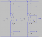
You are using almost the same input I used in my line amp many years ago ( no diamond ). Mine however, is dc coupled. And I was wondering if you have tried your amplifier without capacitors c3,c4,c9,c10?
In my line amp, these would be shorted directly to ground ( they where actually never there in the first place ), and the css's Q7 and Q8 would draw their current from the other side of the two 100 ohm resistors R3 and R4.
Q7 and Q8 then need to draw additional current because the input transistors do not open before the voltage across R3 and R4 go beyond ~0.6 volt.
Meaning the css's should draw an additional 6 mA. I also use a servo to balance my css's for zero offset.
Does my question make sense?
Edit:
All component references are for the schematic shown in post #1
Regards and thank you for sharing
Jørgen
First time stopping by and seeing your amplifier. Looks nice
Hope I am not repeating a question already asked, haven't read all posts yet.
But here we go..
You are using almost the same input I used in my line amp many years ago ( no diamond ). Mine however, is dc coupled. And I was wondering if you have tried your amplifier without capacitors c3,c4,c9,c10?
In my line amp, these would be shorted directly to ground ( they where actually never there in the first place ), and the css's Q7 and Q8 would draw their current from the other side of the two 100 ohm resistors R3 and R4.
Q7 and Q8 then need to draw additional current because the input transistors do not open before the voltage across R3 and R4 go beyond ~0.6 volt.
Meaning the css's should draw an additional 6 mA. I also use a servo to balance my css's for zero offset.
Does my question make sense?
Edit:
All component references are for the schematic shown in post #1
Regards and thank you for sharing
Jørgen
Last edited:
How much do they cost.
Rs.800 per pair.
Hi shaan
First time stopping by and seeing your amplifier. Looks nice
Hope I am not repeating a question already asked, haven't read all posts yet.
But here we go..
You are using almost the same input I used in my line amp many years ago ( no diamond ). Mine however, is dc coupled. And I was wondering if you have tried your amplifier without capacitors c3,c4,c9,c10?
In my line amp, these would be shorted directly to ground ( they where actually never there in the first place ), and the css's Q7 and Q8 would draw their current from the other side of the two 100 ohm resistors R3 and R4.
Q7 and Q8 then need to draw additional current because the input transistors do not open before the voltage across R3 and R4 go beyond ~0.6 volt.
Meaning the css's should draw an additional 6 mA. I also use a servo to balance my css's for zero offset.
Does my question make sense?
Edit:
All component references are for the schematic shown in post #1
Regards and thank you for sharing
Jørgen
Hi Jorgen.
Does either of the two designs in the post (#2) linked below look similar to the design you mentioned?
simulating-building-simple-symmetrical-amplifiers-post2
If yes, then there you have it. This design works pretty well, but due to high sensitivity of the input pair to temperature changes a servo is needed, as you mentioned. With the capacitors installed there however, offset is very tame even if the input pair is not thermally coupled to each other.
Real world tests have been done on the preamp. There is an additional knob besides the volume knob. It varies the harmonics between the two extremes shown in the attached pictures. Looks fun?
Hi Shaan,
Could you please provide more info regarding the harmonics knob preamp
Hi Shaan,
Could you please provide more info regarding the harmonics knob preamp
Will do in time.
Heatsink
Does this heatsink able to handle one channel with 54V rail voltage?
1pcs aluminum E Heatsink for class A Power amplifier DIY 246mm*84mm*25mm | eBay
Does this heatsink able to handle one channel with 54V rail voltage?
1pcs aluminum E Heatsink for class A Power amplifier DIY 246mm*84mm*25mm | eBay
nope!!!!
Take a look here: 40mm Heatsinks – diyAudio Store
For 54 v each rail you need at least 300/120/40 0.4c/w
Take a look here: 40mm Heatsinks – diyAudio Store
For 54 v each rail you need at least 300/120/40 0.4c/w

Thanks Vunce, covering all bases with Class A and AB amp projects for next year. Just waiting on shaan to reply with regards to pcb availability.
Email sent.
I do have the boards and genuine Renesas FETs.
- Home
- Group Buys
- PeeCeeBee V4H GB