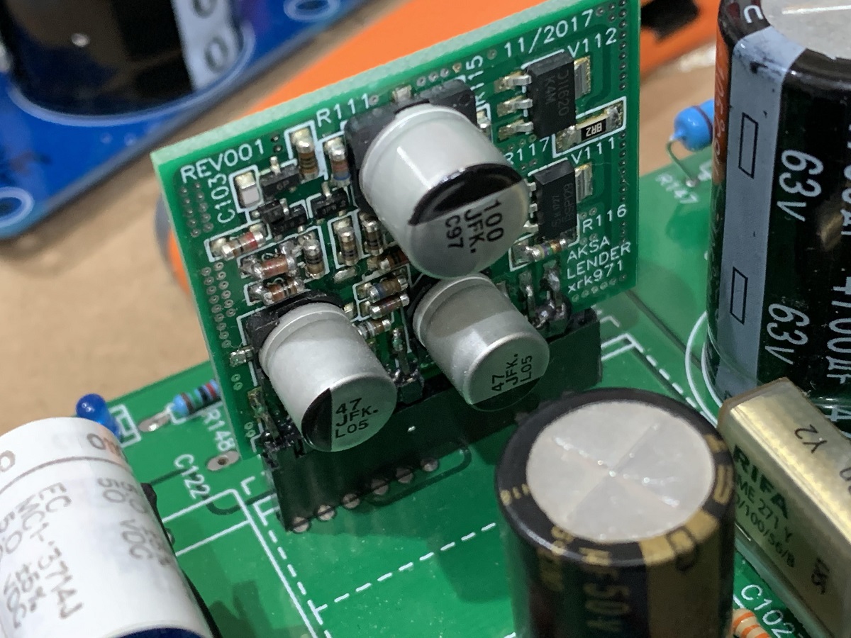
The PCA daughterboard has now been tested and works very well. Listening to it now - driving my M2X (Austin) and W5-2143 XKi speakers.
I am using SK209 JFETs as they are more readily available for new builders trying this out.... about perfect for a preamp or HPA driving cans higher than 100ohms....
What would you recommend for using with 32ohm headphones?
Any of these JFETs will work - the trick is to get about 120mA bias current. With Vcc of 24v and assuming source voltage about half that, dissipation in MOSFET is 1.44w and dissipation I. 4 resistors is same at 1.44w or 366mW ea. So using four 1W resistors should work. Since I have tested the BF862 and IRF610 successfully here - use those settings for best results but drop voltage to 20v. The 2SK209 can work too at higher voltages but will take some trial and error (or a better LTspice model) to get the set points spot on. Looks like you need total 135ohms source resistors. So 560ohms x 4 should work.
Some Aksa Lender TLC
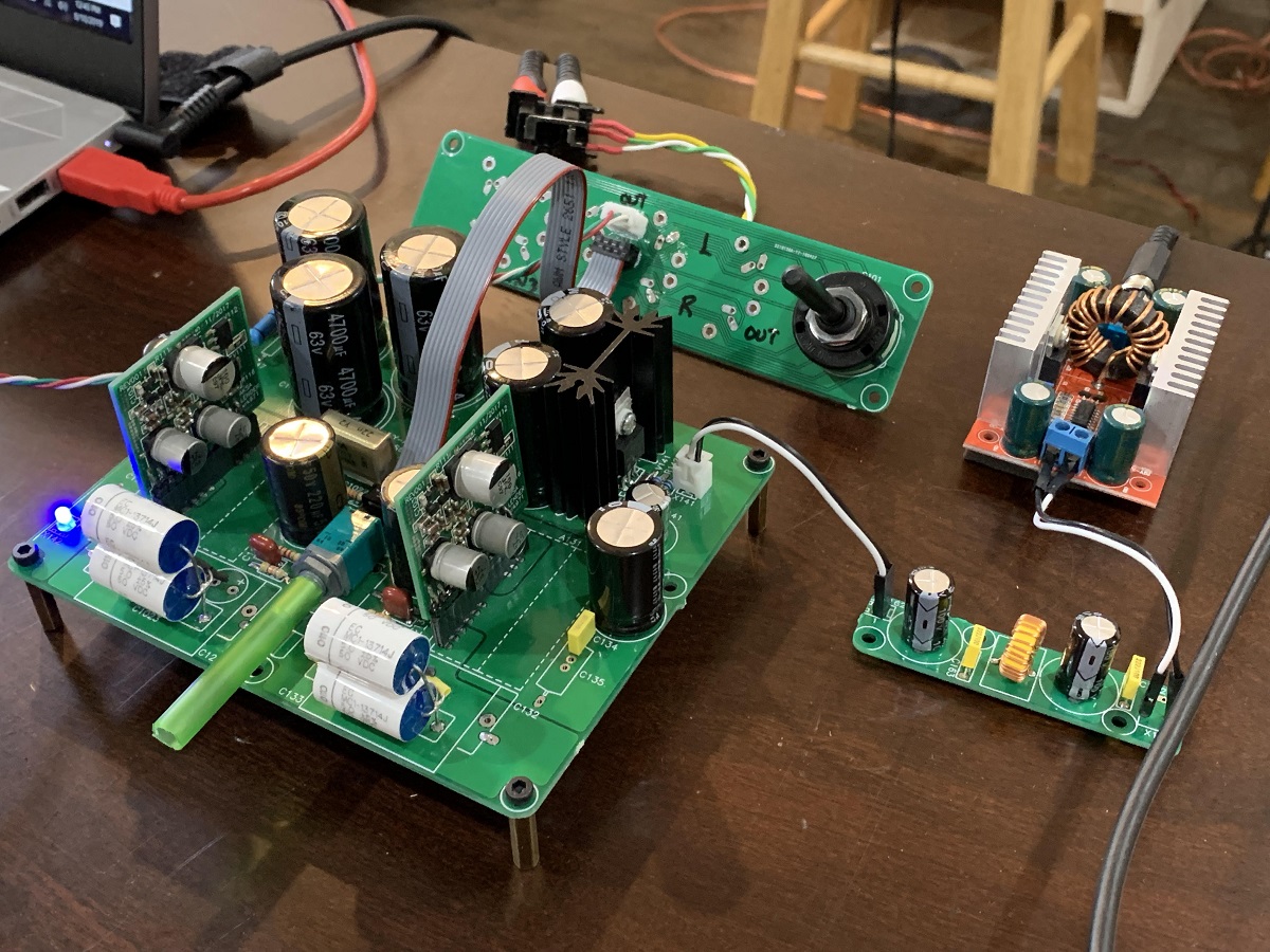
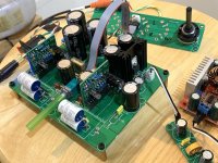
After seeing Vunce working on his Aksa Lender preamp, I pulled out my original one from the verification build (had a lot of cheap caps on it) and cleaned it up. I replaced all the cheap caps with some good stuff. It has a real CRCRC instead of a CRC only; upgraded output caps to Muse 220uF 50v with a Rifa PME (metallized paper safety cap) 22nF 270v Y2 as a bypass cap, and a pair of 5uF 50v metallized polycarbonate caps that Vunce gave me for the input caps. i fixed the cap Mx which had a dead MOSFET, I added the CLC filter (47uF 100v, 22uH, 47uF 100v with a 51R bypass on the inductor). I installed the real flat ribbon cable with 8 conductors and the PCB connectors and added the I/O board with Lorlin 4 position rotary switch. After all this TLC, the preamp has really transformed itself to something even better. The signal integrity with the good 8 wire ribbon cable has really helped the sound. Testing it out as a headphone amp I was really amazed it could drive 55 ohm impedance OB-1's effortlessly. This is actually just set up as a preamp and not HPA yet it works fine as one. The daughterboards are the SMT MELF variety and working very well. I have to say that this combo of caps is very nice - superb detail.
Listening impressions with headphones shows excellent detail and bass with detail in the bass, no noise with source off, great wide sound stage. Very nice... will hook up to drive my VHEX+ in a bit.
Attachments

Last edited:
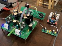
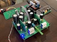
Testing the Aksa Lender with the PCA daughterboards - running at 22.3V at the amp core with 4x 1k source resistors on the MOSFET and 2sk209's for 50mA bias current. Listening to it with VHEX+, and I have to say that it sounds absolutely gorgeous. The soundstage is HUGE and the engagement is transformational. it sounds like a totally different amp - very nice sound. Makes me want to listen to my collection all over again.

This has got to be the most fun one can get for the price of a cheap 2SK209 JFET and an IRF610!
Very very worthwhile addition to the Aksa Lender preamp lineup.")
This has got to be the most fun one can get for the price of a cheap 2SK209 JFET and an IRF610!
Very very worthwhile addition to the Aksa Lender preamp lineup.
Attachments
Nice setup X
I’ve been playing with the PCA in both the Yarra and Aksa Lender. I’m also enjoying how well each preamp sounds with these daughter boards installed. I’ve got a little twist though, the Aksa Lender PCA’s have a 2SK170 installed, the Yarra PCA’s have a 2SK209 installed. No doubt the 2sk209 is cheap as chips but, which transistor version will be preferred??? More listening time needed
I’ve been playing with the PCA in both the Yarra and Aksa Lender. I’m also enjoying how well each preamp sounds with these daughter boards installed. I’ve got a little twist though, the Aksa Lender PCA’s have a 2SK170 installed, the Yarra PCA’s have a 2SK209 installed. No doubt the 2sk209 is cheap as chips but, which transistor version will be preferred??? More listening time needed
Thank you X and Vunce for listening impressions - very encouraging and exciting indeed. I have received my PCA boards but will take a while before I stuff them. Using 2SK209's is also great news for folks who don't want to hunt for unobtainium parts. But this leaves me very undecided - I was planning on using BF862's (still a few in my parts bin), but now I'm not so sure...
Will wait for more feedback before picking a preferred transistor here.
Will wait for more feedback before picking a preferred transistor here.
The gain is set by the ratio of the resistor sum above the JFET divided by the sum value below the JFET (not including the feedback R102). R102 is a feedback resistor to the gate, but the current to the gate can be assumed to be close to zero in a JFET so it doesn't really affect the gain calculation.
From the tabular values for the 3 different JFETs given in the schematic:
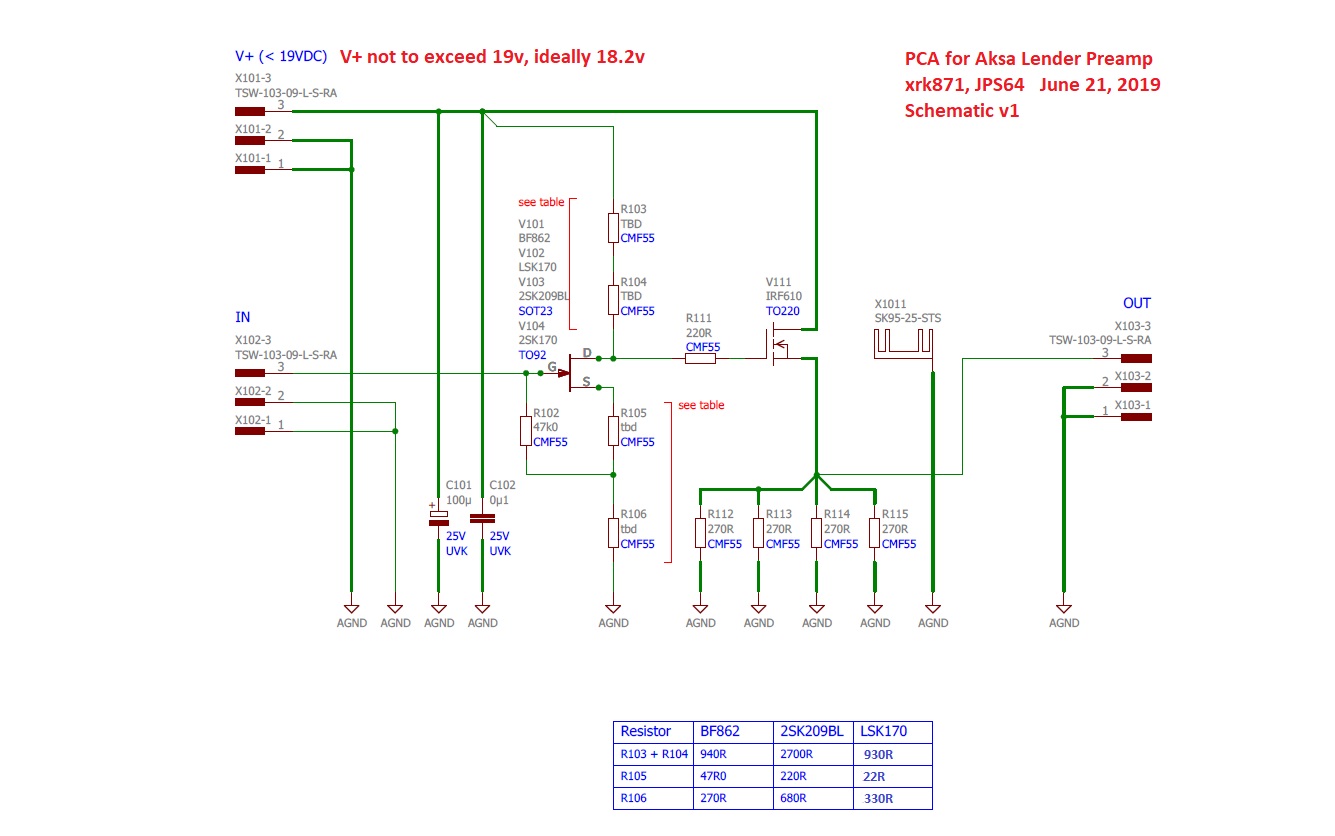
We can see gain for case BF862, we have G=(940)/(47+270)=2.97 or 9.45dB
for the 2SK209, we have G=(2700)/(220+680)=2.97 or 9.54dB
for the 2SK170, we have G=(930)/(22+330)=2.64 or 8.43dB
Why did I not set all the gains the same exact value? The gain value was secondary next to optimizing the correct bias current and harmonic distortion profile via the LTSpice sim. If you want to change the gain, you can try reducing R106 a bit for higher gain, and increasing it a bit to reduce gain, but don't change it too much.
If using 2SK209, you can safely run at higher Vcc (up to 32v even - just adjust R112 to R115 accordingly not to exceed about 125mA and not to exceed 1.5w dissipation over the MOSFET).
From the tabular values for the 3 different JFETs given in the schematic:
We can see gain for case BF862, we have G=(940)/(47+270)=2.97 or 9.45dB
for the 2SK209, we have G=(2700)/(220+680)=2.97 or 9.54dB
for the 2SK170, we have G=(930)/(22+330)=2.64 or 8.43dB
Why did I not set all the gains the same exact value? The gain value was secondary next to optimizing the correct bias current and harmonic distortion profile via the LTSpice sim. If you want to change the gain, you can try reducing R106 a bit for higher gain, and increasing it a bit to reduce gain, but don't change it too much.
If using 2SK209, you can safely run at higher Vcc (up to 32v even - just adjust R112 to R115 accordingly not to exceed about 125mA and not to exceed 1.5w dissipation over the MOSFET).
Last edited:
Vunce and I did some work on tweaking the resistor values last night for 2SK209 "GR" grade JFETs and 2SK170 "BL" grade JFETs to get closer to an ideal quiescent bias current (~40%) relative to the Idss. Values to be posted shortly but circa 2x current values for resistors both above and below the JFET (not including R102 feedback resistor).
Vunce reports that the soundstage really opened up on the 2SK209GR once that fix was in place.
If you have 2SK209BL, the current values are good.
Vunce reports that the soundstage really opened up on the 2SK209GR once that fix was in place.
If you have 2SK209BL, the current values are good.
For Aksa Lender PCA daughterboard builders, here are some good resistor settings to use for 2SK209GR and 2SK170BL JFETs.
The YARRA Preamplifier/HPA for Melbourne DB Group Buy
The YARRA Preamplifier/HPA for Melbourne DB Group Buy
PCA board R102
I received my BOM from Mouser and hope to get my Lender singing with BF862’s this weekend.
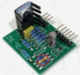
X, looking at your build pictures in post #440 of the PCA daughter boards, I see that resistor R102 (47k) is different – is it carbon film? I know that somewhere in the thread you mentioned the feedback resistor is best to be carbon film.R102 is a feedback resistor to the gate
I received my BOM from Mouser and hope to get my Lender singing with BF862’s this weekend.
Attachments
I am getting some questions on details of the BOM for this preamp and for the cables and connectors and rotary switch. I posted in Post 1 again and repeating here for clarity.
The cable is the 8 pin Male-Male:2205062-2 TE Connectivity / AMP | Mouser
The jack on the PCBs for the cable are female 8 position (one on each end):2178710-8 TE Connectivity | Mouser
The rotary switch is not stocked at Mouser. I ended up getting it on eBay - seearch for Lorlin CK1051
for example: https://www.ebay.com/p/1818269173
- Home
- Group Buys
- AKSA's Lender Preamp with 40Vpp Ouput GB