Eric,
Yes, silkscreen both sides of the PCB might be useful, but as is Marc and Prasi’s PCB is not a problem. Simply place all the tube sockets, small resistors, semiconductors, etc on top (where you have the silkscreen) and the few large caps under the PCB (observing polarity, of course). The small parts are small enough to fit easily between the top plate and the PCB, attached with suitable stand-off spacers. The tubes are sticking through holes in the top plate. See for example Bas’ nice thread on how he built it:
https://www.diyaudio.com/community/threads/oh-no-not-another-baby-huey-el84-build.351919/

You can solder other parts on other side.Hi Prasi
I’m wondering why the tubes sockets are on the wrong side of the PCB...this is bad but I know it’s not you that work on the original PCB.
I bought 4 of these EL84 PCBs not knowing about this...I just found out...that’s a shame.
Picture shown below is an example on how it should be, the pin number must be clockwise.
BR
Eric
Hello Ranko,
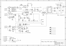
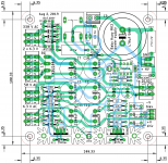
here baby huey mk2 and its psu for your reference.
regards
prasi
here baby huey mk2 and its psu for your reference.
regards
prasi
Attachments
Nice work Prasi.
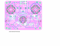
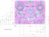
To make it easier to build I would add 5 small holes in the pcb. One in the Center of each tube and the 2 others where the screw of each of the trim pots is located. I’m aware you provided a illustration showing the dimensions but it’s much easier to know exactly where to punch the openings when there’s holes in the PCB.
Just an idea,
Eric
Thanks!Hello Ranko,
here baby huey mk2 and its psu for your reference.
regards
prasi

Please post in English.
Sincerely friends!
Please, can I buy PCBs somewhere else?
Is it possible to obtain a production substrate in the format o that PCB manufacturers accept?
Hello. Since no one has a PCB for Baby Huey anymore, could you please send me the basic graphic documentation for future production?
The current manufacturing companies require graphic layers in vectors and preferably for PCB production in format for GERBER RS274x and for Excelon 2:4 hole drilling
Alternatively, what format did you use when you ordered the PCB production.
Thank you for your quick reply.
The current manufacturing companies require graphic layers in vectors and preferably for PCB production in format for GERBER RS274x and for Excelon 2:4 hole drilling
Alternatively, what format did you use when you ordered the PCB production.
Thank you for your quick reply.
For Sale a set EL34 Baby Huey Amp and PSU MK2 PCB Rev 1.51
https://www.diyaudio.com/community/...-and-psu-mk2-pcb-rev-1-51.388618/post-7080146
https://www.diyaudio.com/community/...-and-psu-mk2-pcb-rev-1-51.388618/post-7080146
PM me, I've a full set of boards with components, optimized transformers and tubes that I can sell.Please consider me interested in a stereo set for BHEL84, if and when they head towards another round.
- Home
- Group Buys
- GB for Baby Huey PCB