Soldering Serpentine is done. I have a 18v transformer. Output of the ssr03 is planned to be 15v.
Now I want to test my work �� what parts do I need to do so?
Are there measuring points on the board availability to measure individual blocks of the board?
I'm scared this won't work out as well as I hoped....If you manage to put everything in the right places then you shall get a stable output voltage and the LED's are lit. Pin 2 and 3 on the opamps shall have the same voltage within a mV or two. The voltage itself shall be 7.5 volts of you want 15 V out and you use a LM431.
What I did is to follow your "BOM ssr03r0(15V LM329)" to get 15V from a Sedlbauer Ringkerntransformator 1 x 230V 2 x 18 V/AC 75 VA 2.08A 82502.
Today I powered up the pcb:
one led lit imediatly I also hear a low pop. No smoke and the second led doesn't lit.
Non Cap bulge and non part explode. I can't see any obvious damage.
Now I realy need help. Are there measuring points on the board availability to measure individual blocks of the board?
How do I test the outcome of the side with the lit LED? How can I narrow down the error on the second side (with straight part numbers)?
How much voltage do you have right now?
Are both sides non-working?
Is the LM329 placed according to the thin outline?
Have you connected the sense inputs?
My recommendation is that you print out on A3 the assembly drawing and do a check that you have the right part in the right spot and also the right direction.
Are both sides non-working?
Is the LM329 placed according to the thin outline?
Have you connected the sense inputs?
My recommendation is that you print out on A3 the assembly drawing and do a check that you have the right part in the right spot and also the right direction.
Sorry for my simple (counter)questions:How much voltage do you have right now?
Are both sides non-working?
Is the LM329 placed according to the thin outline?
Have you connected the sense inputs?
My recommendation is that you print out on A3 the assembly drawing and do a check that you have the right part in the right spot and also the right direction.
Where do I have to measure the voltage. Surly on the X3 named block, but where exactly?...
Let me quote myself: "one led lit imediatly" "the second led doesn't lit" -> so just one side worked; The ones with the odd numbers ;-)
I tried to follow your "ssr03r0_variants.pdf" page 15V, LM329 Assemply Drawings/ ..Pcb.Doc/Top Assam./ Compon.
Clicking on the items there showed my the position of them.
What do you meen with "according to the thin outline"?
Perhaps photos? If, which?
greetings
Last edited:
You have a dual footprint for the reference. Thick outline is for LM431 and the thin is for LM329 (which is written in my text). If you haven't read my documentation I really recommend it.
Can you measure the voltage at:
pin 2, 3, 5 and 6 on the opamp.
output voltage
Can you measure the voltage at:
pin 2, 3, 5 and 6 on the opamp.
output voltage
Attachments
Last edited:
Let me quote myself: I tried to follow your "ssr03r0_variants.pdf" page 15V, LM329 Assemply Drawings/ ..Pcb.Doc/Top Assam./ Compon.You have a dual footprint for the reference. Thick outline is for LM431 and the thin is for LM329 (which is written in my text). If you haven't read my documentation I really recommend it.
Can you measure the voltage at:
pin 2, 3, 5 and 6 on the opamp.
output voltage
Clicking on the items there showed my the position of them.
I think this is a very good kind of " interactiv" pdf. So I have used the thin for LM329 position. Still, I've probably managed to make mistakes....
I did follow your "Building directions" or the "flatter the sooner" rule.
I do have a Multimeter, I do see the N1 and 2 OpAmp, and because of the mentiones pdf I knew where pin1 is. What I didn't know where do I have to put the measuring tips of the multimeter? One at pin2 and the second one?
No measuring points at Block X3 at this time?
Last edited:
Thanks dor the picture. I us it for my own purposes.
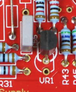
First thing I noticed the second LED lit also, but not that bright. sorry for that.
Second thing I noticed were two solder bridge. Maked within die picture. After removing these the second led was brighter. Is this possible?
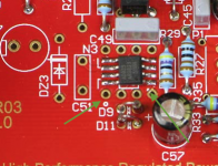
I name the holes N1-1; N1-8 acording to the opamp leg near by.
the voltage I measured:
N1-1: 2:1,87; 3:1,85; 5: 0; 6:5 rising
N1-8: 2, 3, 5, 6:0
N2-1: 2:1,82; 3:1,85; 5: 0; 6:0
N2-8: 2, 3, 5, 6:0
I meeasured also -Vout = 19,95 and +Vout = 0 against ground
All DC!
did this make sence?
An externally hosted image should be here but it was not working when we last tested it.
First thing I noticed the second LED lit also, but not that bright. sorry for that.
Second thing I noticed were two solder bridge. Maked within die picture. After removing these the second led was brighter. Is this possible?
I name the holes N1-1; N1-8 acording to the opamp leg near by.
the voltage I measured:
N1-1: 2:1,87; 3:1,85; 5: 0; 6:5 rising
N1-8: 2, 3, 5, 6:0
N2-1: 2:1,82; 3:1,85; 5: 0; 6:0
N2-8: 2, 3, 5, 6:0
I meeasured also -Vout = 19,95 and +Vout = 0 against ground
All DC!
did this make sence?
An externally hosted image should be here but it was not working when we last tested it.
Finished soldering the boards with parts from 24V BOM, LM431. Now im waiting for the transformer for testing. Very nice boards and easy build so far.
I used terminal blocks 651-1864451 and 651-1864477 from mouser(along with all the other parts). My heatsinks are smaller than in BOM, i might end up attaching them to the chassis(when i order and get it).
Negative side
Positive side
Both sides
NoDo you have a tin drop in J1-J4 on the solder side?
It is not mentioned at "ssr03r0_variants.pdf" 15V, LM329 Assemply Drawings/ ..Pcb.Doc/Top Assam./ Compon. (page 30)
Do I have to?
Last edited:
ok, will do thisYes, they must always be connected, either on the pcb or in a remote sense application.
just for understanding was is the functional different between R25,26 = Wire jumper and J1,2,3,4 = tin Jumper?
For 15 volt you should only have one LED on each half. Do you really use the 15 V BOM?
Pin 7 is interesting (not pin 5). What is the voltage on this pin?
What is the voltage across the LM329?
Are both halves behaving the same?
Is it possible?
+Vout against gnd = +15,85V
-Vout against gnd = -15,85V
first hope germinates...
Are there any measure point I could check?
https://s14.postimg.org/wrrktj6z5/IMG_20180130_150654000_HDR.jpg
https://s14.postimg.org/sve8xijep/IMG_20180130_150403994_HDR.jpg
I think I need a lot of praxis to get better...
Last edited:
If the voltage on pin 2 and 3 on the opamp is the same with a few millivolts, then the regulator works properly. A small remarks about your soldering joins, warm more and let the tin float through the hole. Right now it's too much tin and not heated up enough. Otherwise, good work. Don't forget to solder the heatsinks.
If the voltage on pin 2 and 3 on the opamp is the same with a few millivolts, then the regulator works properly. A small remarks about your soldering joins, warm more and let the tin float through the hole. Right now it's too much tin and not heated up enough. Otherwise, good work. Don't forget to solder the heatsinks.
Pin 2+3 are the same
but they are different on the "+" and "-" side of the pcb
is this OK?
at the soldering joins I will work again.
at the end of the day it seams so that I managed to finish my first real DIY soldering ;-)
Thank your for your support and patient with me.
- Status
- This old topic is closed. If you want to reopen this topic, contact a moderator using the "Report Post" button.
- Home
- Group Buys
- Group buy: SSR03 Super Regulator Power Supply Board