and now the SSR03-5V: (TT is delivering 9V)
none (!) of the four LED are on
tin drops on J1-J4: YES
X3: no load resistor parallel installed
+ -> gnd: 8,90V DC
- -> gnd: 8,68V DC
opamp N2: results in DC
counting order: dot is 1, then going down the side =4; other side 5, going up=8
the second measuring tip is at X3-gnd;
pin 2: 3,69V
pin 3: 3,07V
pin 4: 9,42V
pin 6: 1,06V
pin 7: 0 V
opamp N1:
pin 2: 3,75V
pin 3: 3,13V
pin 4: 0
pin 6: 1,01V
pin 7: 9,75 V
... and as I told you, you must adjust the current limit since it's set to 300 mA. I recommend that you check the real consumption first.As said before: The ssr03 should deliver 400mA@17V
I don't have any measured values yet, because I need a working power supply. ;-)... and as I told you, you must adjust the current limit since it's set to 300 mA. I recommend that you check the real consumption first.
This is what I have from the DCG3 designer Salsa:
"The DCG3 can go 300mA pk per channel at +/-17V. In other words 10W pk power ch i.e. 5W pk power each rail worst case draw in high bias (Ib 150mA) builds."
My understanding is 300mA@17V + 50mA for a AMB "epsilon12" protection board.
To test the PSU in advance I bought the 47ohm load resistors.
Last edited:
... and as I told you, you must adjust the current limit since it's set to 300 mA. I recommend that you check the real consumption first.
I don't have any measured values yet, because I need a working power supply. ;-)
This is what I have from the DCG3 designer Salsa:
"The DCG3 can go 300mA pk per channel at +/-17V. In other words 10W pk power ch i.e. 5W pk power each rail worst case draw in high bias (Ib 150mA) builds."
My understanding is 300mA@17V + 50mA for a AMB "epsilon12" protection board.
To test the PSU in advance I bought the 47ohm load resistors.
I have the impression that you may have to iteratively hit exactly the point where V and mA macht your requirements?
If so, to work with the mentioned 350 - 400mA@17V is not sufficient?
How do I get on here?
How do I get these 2,V on pin3?The 5 V regulator shall have 2.5 volts on the pin 3.
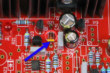
Is the LED in the DZ1, DZ2 position in the right direction?
Are there any other measurement that I can deliver to you to fix this?
I hope I did the LED's right... How do I check this now?
The current limitation must be set to cover your needs. R47 and R48 must be tuned. 0.65/I = RI have the impression that you may have to iteratively hit exactly the point where V and mA macht your requirements?
If so, to work with the mentioned 350 - 400mA@17V is not sufficient?
How do I get on here?
350 mA = 1.8 ohm
If you solder 12 ohms in parallel, then you will have 1.8 ohms. You can remove the 2.2 ohm and replace it with 1.8 ohm but the risk is that you will damage the pcb.
You can test the LED using diode test on your DVM. Make sure the regulator is unpowered. Compare the schematic symbol. See the picture. With diode test you should have a weak light from the LED. The cathode shall be facing down.
I do have one LED left: results with the DVM: 1770
When changing from DZx to Hx, I have to swapp the measuring tips.
When changing from DZ1 to DZ2 or H1 to H2, I do not have to swapp the measuring tips.
build in H1: 720
build in DZ1: 1650
build in H2: 720
build in DZ2: 1650
is it possible that at position H1+2 I allways get a result?Are the DZ1 and DZ2 oriented in the right direction also? The cathode marking, where do you have it?
in one position I get 1770. when I swap the tips I get 720?
At DZ1+2 only in one position I get numbers.
DZ1+2 hase the right polarity
Last edited:
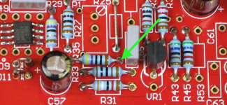
x3-gnd and r35 right is 2,5V on both sidesWhich voltage do you have on the right side of R35? The net called VREF. In this point you should have 2.50 V
Good but what about the LED? Do you have it in the right direction? Notice that most LED's has a straight surface at the cathode but some has this between the pins. How many volts do you have across the LED? If you have more than 1.6-1.8 V then you have the LED in the wrong direction. The long pin is anode and the short one cathode but I'll guess you have them cut off already.
x3-gnd and r35 right is 2,5V on both sides
You still have
opamp N2
pin 2: 3,69V
pin 3: 3,07V
opamp N1:
pin 2: 3,75V
pin 3: 3,13V
You have 3,07-313 V on the left side of the R35?
Good morning ;-)
I do have R34left 3,03 and R35left 3,09V
R34+35 right 2,51V
N1p2: 3,70
N1p3: 3,07
N2p2: 3,66
N2p3: 3,03
DZ1+2 I have 7,8V
just for info: none of the LEDs are on
I do have R34left 3,03 and R35left 3,09V
R34+35 right 2,51V
N1p2: 3,70
N1p3: 3,07
N2p2: 3,66
N2p3: 3,03
H1+2 I do have 1,6VHow many volts do you have across the LED? If you have more than 1.6-1.8 V then you have the LED in the wrong direction.
DZ1+2 I have 7,8V
just for info: none of the LEDs are on
Last edited:
With a hot air dryer it was then no longer soooo difficult to remove.
H1+2 and DZ1+2 should show 1.6V, right?
The cathode (straight surface / short pin) at H1 points inwards. The one from DZ1 to the outside, right?
H2 and DZ2 just the oposite, right?
I may have installed the DZx LEDs upside down again. But I still get 1,6V for Hx and 7V for DZx.... ;-(
sorry for being so complicated...
Last edited:
It's very good to be sure when you mount a part, not almost sure. Long pin is "plus" or "anode". Compare the pcb layout and the schematics in order to be really sure. Since the pcb only has two layers you can see exactly how it's designed.
The flat surface of the cathode marking shall be in one direction for all LED's.
Notice that you have already succeeded to get this working and by this managed to mount the H1 and H2 correctly. This 5 V version has the DzX changed to LED's so this is the difference. Take one more look into post 167 and look at the picture.
Attachments
Last edited:
Am I right that the long legs are always on top of the pictures?
If yes it is more than possible that I have them in the wrong direction...
above H1+2 is shown a "+". for me this is the Anode long leg. That I have.
below the text DZ1+2 is horizontal line. For me that is the cathode / short leg. Wrong?
If yes it is more than possible that I have them in the wrong direction...
above H1+2 is shown a "+". for me this is the Anode long leg. That I have.
below the text DZ1+2 is horizontal line. For me that is the cathode / short leg. Wrong?
- Status
- This old topic is closed. If you want to reopen this topic, contact a moderator using the "Report Post" button.
- Home
- Group Buys
- Group buy: SSR03 Super Regulator Power Supply Board