I need one too..I'll take VenusFly seat.
I am confused at the input selection. Where can I get USB to Simultaneous board?
Hi guys,
Check this out.
pedjas USB to simultaneous converter.
Or you could use Ian Canada's i2s to pcm converter.
Ryan
Check this out.
pedjas USB to simultaneous converter.
Or you could use Ian Canada's i2s to pcm converter.
Ryan
Cannot use a standar linear power supply?
Yes you could, just make sure its outputs are floating. Low noise is also a desirable specification.
Hi Guys,
A few people have messaged me with queries about how to power the 26V floating supply.......
Ryan
I am little confused. I have never used a floating supply before.
What if I use a bipolar supply of +V, 0, -V DC to make floating power supply? I’ll set it for +13, 0, -13 VDC operation and will use +13 and -13 without using the 0 common ground. This way between +13VDC and -13VDC, I’ll get 26VDC floating. Is it safe this way?
Thank you so much Ryan.
I am clear that linear sources of low noise are necessary. My idea is to buy adjustable linear power sources and adjust them to the necessary voltage. But I would need to know how many amps are needed for each source to decide for the best.
I understand that two linear sources are needed, one of x and one of x. What I do not understand is what the & nbsp; of the outputs of 26v and 8v.
I have read the thread of the pcb several times to understand it but I have come to the conclusion that I am not very ready for this and that my lousy English does not help at all.
Thank you very much for your patience.
If at the end I get everything working well you will have a bottle of good Spanish wine in your house, it's a promise")
Best regards.
I am clear that linear sources of low noise are necessary. My idea is to buy adjustable linear power sources and adjust them to the necessary voltage. But I would need to know how many amps are needed for each source to decide for the best.
I understand that two linear sources are needed, one of x and one of x. What I do not understand is what the & nbsp; of the outputs of 26v and 8v.
I have read the thread of the pcb several times to understand it but I have come to the conclusion that I am not very ready for this and that my lousy English does not help at all.
Thank you very much for your patience.
If at the end I get everything working well you will have a bottle of good Spanish wine in your house, it's a promise
Best regards.
Hi Gents,
To test if a PSU is floating or not:
Fount at : measurement - How to check if a DC power supply is a floating source? - Electrical Engineering Stack Exchange
Connect a pair of identical resistors in series and connect the free leads of the resistors to the power supply output terminals. Connect the middle connection of the series resistors to earth ground.
Measure the voltage across each of the series resistors. The voltage should be identical across each resistor.
Pick the resistor value such that you get about 100mW dissipation in each of the resistors.
Thank you so much Ryan.
I am clear that linear sources of low noise are necessary. My idea is to buy adjustable linear power sources and adjust them to the necessary voltage. But I would need to know how many amps are needed for each source to decide for the best.
I understand that two linear sources are needed, one of x and one of x. What I do not understand is what the & nbsp; of the outputs of 26v and 8v.
I have read the thread of the pcb several times to understand it but I have come to the conclusion that I am not very ready for this and that my lousy English does not help at all.
Thank you very much for your patience.
If at the end I get everything working well you will have a bottle of good Spanish wine in your house, it's a promise
Best regards.
I appreciate the sentiment. =)
The 8V supply draws 45mA
the 26V supply draws 135mA
What do you mean by "What I do not understand is what the & nbsp; of the outputs of 26v and 8v."
I'm not 100% sure how that would work, depends on the topology. Just test it with dummy loads (around 200 ohms 5W). And also test if floating using the above method.
I am little confused. I have never used a floating supply before.
What if I use a bipolar supply of +V, 0, -V DC to make floating power supply? I’ll set it for +13, 0, -13 VDC operation and will use +13 and -13 without using the 0 common ground. This way between +13VDC and -13VDC, I’ll get 26VDC floating. Is it safe this way?
What do you mean by "What I do not understand is what the & nbsp; of the outputs of 26v and 8v."
Sorry, I wrote that very early and with a little hangover from that Spanish wine hahaha.
Also I was wrong. I wanted to know what the -15 V out and -5v out function is. now I apologize for the mistake (in the end I will have to send a box of wine bottles).
Many thanks Ryan.
Jorge
Floating regs/psu
Found a couple of examples of floating regulator/Psu on the Zen > Cen > Sen thread post #418 (only 18v but I presume easily changed by adjusting the values of relevant resistors)
Zen -> Cen -> Sen, evolution of a minimalistic IV Converter
Was fortunate to recently get some new toys and so today was soldering up a D1 I/V and a Sen I/V to try with this DAC
Mods= please move if not appropriate here.
I know there has been interest from others in this GB in the IV that RyanJ is using, namely the Cen.
I have surplus to my requirements
1x Xen Audio designed Cen All JFET PCB
1x pair TO-92 heatsinks (hard to come by)
You will need to source and match your own jfets.
Happy to send in exchange for other audio related pcb
Attachments
I need a Sen. single ended correct?Mods= please move if not appropriate here.
I know there has been interest from others in this GB in the IV that RyanJ is using, namely the Cen.
I have surplus to my requirements
1x Xen Audio designed Cen All JFET PCB
1x pair TO-92 heatsinks (hard to come by)
You will need to source and match your own jfets.
Happy to send in exchange for other audio related pcb
Hi!
I'm still very clueless with the 26 volt floating source, to see if I understand it now.
Would I serve any linear source even if I have references to GND whenever that source has no contact with any other than if I work with GND?
What I want to know is if it would serve a linear source like this (which has GND):
Module d'Alimentation Lineaire Regule LM317 / MJ15025G 3.3V a 33V DC 5A - Audiophonics
whenever you connect it only and exclusively to the secondary of a transformer that only feeds this linear source. So by + exits only positive voltage and GND comes out only the negative voltage.
Is this right or do I definitely not find out anything?
Has anyone found a commercial power supply that can serve if you do not serve?
I have stopped my project for this and I start to be desperate, despite the great help and patience of Ryan and other friends who help me.
Thank you all very much.
Hi Jjazz,
Yes that would work, as long as those mounting holes are isolated from your system GND by using nylon standoffs/bolts. In this case the GND output would serve as the negative when isolated from GND. This supply is rated at 5 amps, you only need 135mA.
I think you're on the right track
What I want to know is if it would serve a linear source like this (which has GND):
Module d'Alimentation Lineaire Regule LM317 / MJ15025G 3.3V a 33V DC 5A - Audiophonics
Yes that would work, as long as those mounting holes are isolated from your system GND by using nylon standoffs/bolts. In this case the GND output would serve as the negative when isolated from GND. This supply is rated at 5 amps, you only need 135mA.
Is this right or do I definitely not find out anything?
I think you're on the right track
Thank you very much Ryan.
I guess the answer is no, but 25v could be used instead of 26v?
I have found these sources of power and regulators of very very low noise:
ULN-PS2 Ultra Low Noise Dual Positive Power Supply
http://vi.raptor.ebaydesc.com/ws/eB...=122649&pm=1&ds=0&t=1509809196623&cspheader=1
Best regards
I guess the answer is no, but 25v could be used instead of 26v?
I have found these sources of power and regulators of very very low noise:
ULN-PS2 Ultra Low Noise Dual Positive Power Supply
http://vi.raptor.ebaydesc.com/ws/eB...=122649&pm=1&ds=0&t=1509809196623&cspheader=1
Best regards
I guess the answer is no,
No, you could use that supply, just make sure the GND output is isolated - floating.
but 25v could be used instead of 26v?
No, aim between 26V and 27V.
I have found these sources of power and regulators of very very low noise:
ULN-PS2 Ultra Low Noise Dual Positive Power Supply
I wouldn't use a dual supply because the GNDs may be connected meaning you couldn't use it for both the 8V and 26V supplies.
Sounds expensive and overkill.
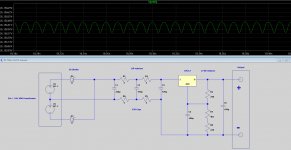
Why not just get some verro board, diodes, resistors, and caps and have a go at building your own?
I've attached a sim of a circuit that is easy to build yourself on vero board. It sims at under 200uV ripple.
Ryan
Attachments
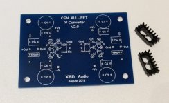
Mods= please move if not appropriate here.
I know there has been interest from others in this GB in the IV that RyanJ is using, namely the Cen.
I have surplus to my requirements
1x Xen Audio designed Cen All JFET PCB
1x pair TO-92 heatsinks (hard to come by)
You will need to source and match your own jfets.
Happy to send in exchange for other audio related pcb
Thank you to those who expressed interest in this PCB and heatsinks.
I am very happily swapping it for a DCB1 Hypnotise PCB that was offered in exchange. Sorry I only had one to offer. Happy building.
- Status
- This old topic is closed. If you want to reopen this topic, contact a moderator using the "Report Post" button.
- Home
- Group Buys
- Distinction-1541 v2 complete PCB interest list