I'm trying to get some insight into how much inrush there is and how it limits it. It seems to work with your directives, but breaks down if I add 'skip initial operating point solution.' Actually it might be your sim that's the cause since that breaks down too.
Don't see any Spice things in the SLB thread.
Don't see any Spice things in the SLB thread.
It was actually from a different thread and never posted. Here is the sim by jhofland for a Darlington based BJT cap multiplier based on a design by Mark Johnson so you can see how to do it. Plot the Vload vs time and you can see how it slowly rises and is low ripple.
Attachments
Thanks. I am still wrestling with it.
One thing I can say though is that R5 330Ω sounds absolutely awful despite what the simulations suggests. Of course I also don't know how to read the simulation very well, but it sounds bad regardless.
I'd like to try 240Ω but it doesn't look like I have thin films in compatible packages and not sure if my mild OCD will allow me to use a thick film.
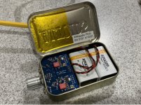
For those who want a box or just an enclosure case for the pocket amp to convert this to desktop use without much fiddling I have some STLs attached.
Basically I did this as I had a crap ton of Thinkpad power supplies laying around and I didn't use this amp portably as much as I thought I would.
Pocket Amp Desktop Conversion by hifiguy99 - Thingiverse
You just these three things:
- TPS7A4700 Ultralow-noise (4µVrms) Power Supply 1.4-20.5V,1A for Audio DAC (there is a ebay listing for this not sure if I am allowed to post it, specify you want a 17V output in the notes otherwise you can adjust it yourself)
- Thinkpad T510 Power Jack (used this one because it came with a screw out of the other thinkpad supplies)
- And obviously my enclosure
Optional:
3mm x 3mm round magnets for the lid. I found the friction fit is good enough but it doesn't hurt to glue in some magnets.
Some pics attached:
Neat idea HiFiGuy! The PCA makes a great preamp as you probably know. Makes any solid state class AB amp or Class D amp sound better.
Thanks for sharing your STL.
No Problem!
and to be honest I am using it directly to the HD 600s I have and it sounds good as is. Way better than the ****** headphone out on the Behringer interface I have. You did a good job on the PCA design
")
Here is a lower cost TPS7A regulator module.
US $11.17 12% Off | TPS7A4701 TPS7A3301 Low Noise RF Linear Voltage Regulator DAC ADC Audio decoder Power Supply DC-DC 5V 12V Module for amplifier
TPS7A4701 TPS7A3301 Low Noise RF Linear Voltage Regulator DAC ADC Audio decoder Power Supply DC DC 5V 12V Module for amplifier|Replacement Parts & Accessories| - AliExpress
Is there a USB 5V charger circuit that could be used with one of these batteries -
.
3.7V 12500mAh lithium polymer battery 8080130 MP3 MP4 navigation instruments small toys and other products Universal Battery|Digital Batteries| - AliExpress
.
- and one of the Regulator Modules you mentioned, to allow the PCA (or a pair of them, as a Balanced Amp) to run from USB, or the 3.7V Li-Po battery? Thanks!
.
3.7V 12500mAh lithium polymer battery 8080130 MP3 MP4 navigation instruments small toys and other products Universal Battery|Digital Batteries| - AliExpress
.
- and one of the Regulator Modules you mentioned, to allow the PCA (or a pair of them, as a Balanced Amp) to run from USB, or the 3.7V Li-Po battery? Thanks!
Yes, examples in this thread already. Look for “LiPo USB charger DIY”
For example:
McIgIcM 10pcs TP4056 1A Lipo Battery Charging Board Charger Module Lithium Battery DIY Micro Port Mike USB https://www.amazon.com/dp/B06XXYTRGK/ref=cm_sw_r_cp_api_glc_fabc_G1dbGb59WZ0EC
You will need DCDC step up to make 18v from that too.
Or get this and it charges and boosts output as high as 24v.
daier 5Pcs 2A USB 18650 Lithium Li-ion Battery Charger Module Boost 3.7V to 5V 9V 12V https://www.amazon.com/dp/B07SBZZ5SC/ref=cm_sw_r_cp_api_glc_fabc_-5dbGbQTVKEY8
Here is a lower cost TPS7A regulator module.
US $11.17 12% Off | TPS7A4701 TPS7A3301 Low Noise RF Linear Voltage Regulator DAC ADC Audio decoder Power Supply DC-DC 5V 12V Module for amplifier
TPS7A4701 TPS7A3301 Low Noise RF Linear Voltage Regulator DAC ADC Audio decoder Power Supply DC DC 5V 12V Module for amplifier|Replacement Parts & Accessories| - AliExpress
XRK971,
This has me thinking. Now that I am basically running a desktop setup, what bias current should I shoot for since I don't care about battery life? Running 300 Ohm HD600s, but I might buy some 150 ohm cans (HD 660s). I matched my FETs and this is the voltage I got:
8.095 on side A
8.050 on side B
Corresponds to a bias current of:
68.9 mA on side A
68.5 mA on side B
Is this well matched? or should I change R5/R4/put a parallel resistor to fix things.
Is this fine for high impedance cans? I just want whatever has the lowest THD/sounds the best.
Thanks
Are you using a PCB from my shop or making your own? Try to get close, doesn’t have to be exact. But the 67ohm value you see is the result of paralleling 4x 270ohm resistors to allow the power dissipation. There’s a lot of heat there.
If you don’t like looking for parts on Mouser (that’s what 75% of the work on a DIY project is btw), you can order the kit that has all the parts for you from my shop.
Actually, I am not sure where you see 67ohms on my circuit?
We aren’t asking you to learn electrical engineering. Just at least know the concept of how to calculate the values of resistors in series vs parallel.
Series you add them up. Parallel, you multiply them and divide by their sum. This simplifies if using the same values in parallel: two 100ohms in parallel is 100/2 or 50ohms. Four 270ohms in parallel is 270/4 or 67 ohms.
For capacitors it is the opposite. When in parallel they add. When in series you do what we did with resistors in parallel.
You also need to know Onms law: V = I x R and it’s variants P = V^2/R and P = I^2 x R
Where V is voltage, I is current in amps, R is resistance in ohms, and P is power in watts. You need that to estimate how big of a resistor you need when ordering one.
For example, in the PCA, the bias current through the MOSFET and source resistor is 70mA. That’s 0.07A. How much power is dissipated in the parallel 4x 470ohm source resistors?
470/4 is 117.5 or 118ohms. Use P = I^2 x R we get 0.07A^2 x 118ohms = 0.58w. Not an insignificant amount of heat. A 1/2w resistor would get smoked. Which is why I use 4x 1/4w for a 1W rating and we run at about half of the max so all is good.
Only an hour? Every hobby has time you need to put into it to learn the craft. I’m afraid you are looking for a premade kit all ready to solder. That is available if you want.
This amp is one of the simplest you will ever build. So it’s really not that much compared to most projects. Well, I do have a single transistor amp but that’s a different animal.
If you don’t like looking for parts on Mouser (that’s what 75% of the work on a DIY project is btw), you can order the kit that has all the parts for you from my shop.
Actually, I am not sure where you see 67ohms on my circuit?
I don't have enough time to learn electrical engineering, could you please just tell me the answer like I hardly know how to solder?
We aren’t asking you to learn electrical engineering. Just at least know the concept of how to calculate the values of resistors in series vs parallel.
Series you add them up. Parallel, you multiply them and divide by their sum. This simplifies if using the same values in parallel: two 100ohms in parallel is 100/2 or 50ohms. Four 270ohms in parallel is 270/4 or 67 ohms.
For capacitors it is the opposite. When in parallel they add. When in series you do what we did with resistors in parallel.
You also need to know Onms law: V = I x R and it’s variants P = V^2/R and P = I^2 x R
Where V is voltage, I is current in amps, R is resistance in ohms, and P is power in watts. You need that to estimate how big of a resistor you need when ordering one.
For example, in the PCA, the bias current through the MOSFET and source resistor is 70mA. That’s 0.07A. How much power is dissipated in the parallel 4x 470ohm source resistors?
470/4 is 117.5 or 118ohms. Use P = I^2 x R we get 0.07A^2 x 118ohms = 0.58w. Not an insignificant amount of heat. A 1/2w resistor would get smoked. Which is why I use 4x 1/4w for a 1W rating and we run at about half of the max so all is good.
Is there any way you could add a premade cart so I don't have to spend an hour trying to figure out which things to get
Only an hour? Every hobby has time you need to put into it to learn the craft. I’m afraid you are looking for a premade kit all ready to solder. That is available if you want.
This amp is one of the simplest you will ever build. So it’s really not that much compared to most projects. Well, I do have a single transistor amp but that’s a different animal.
Last edited:
Where do I see 67 ohms on the instructions? What does 67R in "R4 33R (1%) ** use 67R for 2SK209GR **" mean?
I only have so many hours in a day and I want to focus them on the skills that I want to improve and my skill at doing so is pretty crap. I get overwhelmed easily and tend to give up on things. Your saying I should learn enough that I can understand what you just wrote and enough to just figure it out myself. I have a phono preamp that a guy told me to just figure it out with too. I never completed it. I hate it when people tell me to do many hours of work to rather then just tell me the answer that would take them seconds to do. I made a cart on mouser in ten seconds. I'd love to have the patience and mental capacity to do that but I don't. I regret buying your product. I'm sorry for bothering you.
I only have so many hours in a day and I want to focus them on the skills that I want to improve and my skill at doing so is pretty crap. I get overwhelmed easily and tend to give up on things. Your saying I should learn enough that I can understand what you just wrote and enough to just figure it out myself. I have a phono preamp that a guy told me to just figure it out with too. I never completed it. I hate it when people tell me to do many hours of work to rather then just tell me the answer that would take them seconds to do. I made a cart on mouser in ten seconds. I'd love to have the patience and mental capacity to do that but I don't. I regret buying your product. I'm sorry for bothering you.
Ok, you mean this schematic? I thought you were talking about the original circuit for BF862. Please refer to a schematic or post number when asking questions about certain part values.
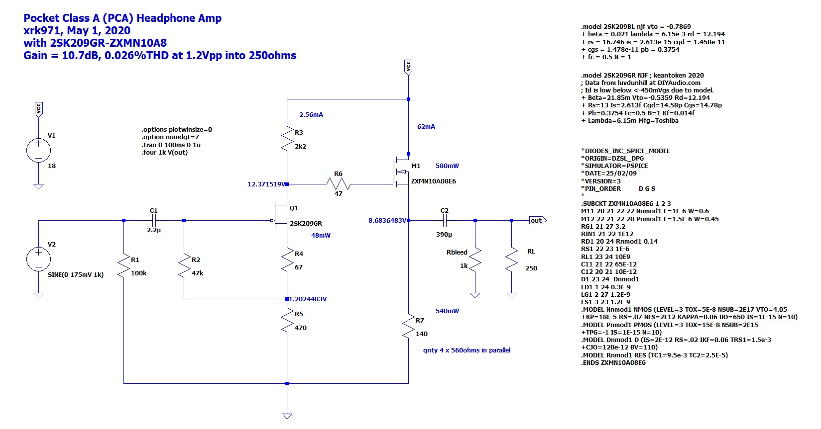
In this case, 67ohms is a typo - sorry about that. Please use 68 ohm which is a standard value. Most of these values don't have to be exact. Within 5% is fine.
Here is the BOM that I gave next to that post:
To get these parts, go to Mouser and type in this for the various resistors: "0805 100k 1% Yageo", you will get something like this:
AC0805FR-7W100KL YAGEO | Mouser
repeat this for each value of the resistor: 47k, 2k2k, 68R, 270R, 470R, 15k
For the SMT capacitor, type in the search bar "1206 100nF 100V X7R" and you get this:
https://www.mouser.com/ProductDetai...EpiMZZMukHu%2BjC5l7YWY0Wy3FSR3Vjzcm4Uv%2BxH8=
I gave you the part number for the other ones. Sure, it will take you about an hour to type all this. Maybe less. Someone might have a ready to go shopping cart for you already. I'm sorry I don't because I have all of these parts already and they were bought here and there, or combined with the BOM of another project, never on a single shopping cart otherwise I would give it to you.
I hope that helps.
Regards,
X
In this case, 67ohms is a typo - sorry about that. Please use 68 ohm which is a standard value. Most of these values don't have to be exact. Within 5% is fine.
Here is the BOM that I gave next to that post:
All resistors 0805 package, metal thick film, 1% on specified parts, else 5%. Yageo 1% 0805 SMT from Digikey are $0.77 for 100
R1 100k (5%)
R2 47k (1%)
R3 1k (1%) ** use 2k2 for 2SK209GR **
R4 33R (1%) ** use 67R for 2SK209GR **
R5 270R (1%) ** use 470R for 2 SK209GR **
R6 47R (5%)
R7_1 470R (1%)
R7_2 470R (1%)
R7_3 470R (1%)
R7_4 470R (1%)
RL 270R (5%) User select (optional, use for higher current draw on amp)
RLED 12k or 15k (5%) Current limit for LED, 15k or value according to supply voltage
C1 Input cap 5mm pitch up to 5.5mm wide (Wima 2.2uF MKS2B042201F00JSSD)
C2_1 Output cap 3.5mm pitch, 8 dia (390uF 20v Panasonic OSCON 20SEPF390M) or Nichicon AK 470uF if you can fit it Edit: I highly recommend a 1000uF 16v OSCON here for low impedance phones.
C2_2 Output cap 5mm pitch, up to 9mm wide (Wima 1uF MKS2C041001F00KSSD) Edit: I highly recommend a second 1000uF 16v OSCON here, if you have 30ohm or lower phones, and place Wima on SMT side.
C3 Rail cap 100uF 3.5mm pitch, diameter whatever you can fit in the tin (100uF 20v Panasonic OSCON 20SEP100MX) - or highly recommended Nichicon 2200uF 16v - lay on its side
C4 Rail cap 100nF 1206 package (50v X7R)
C5 Additional 100nF rail cap 1206 package (50v X7R)
Q1 BF862 (771-BF862-T/R) *** if BF862 not available Use 2SK209GR ***
M1 ZVN4306GTA *** if ZVN4306 not available, a great alternative is ZXMN10A08GTA ***
Switchcraft 3.5mm stereo jacks x2 (35RAPC4BV4)
Alps 10kOhm stereo pot with power switch (RK0971221Z05)
3mm round LED (red or green)
4-pin 2.54mm pitch power connector (see post #44)
To get these parts, go to Mouser and type in this for the various resistors: "0805 100k 1% Yageo", you will get something like this:
AC0805FR-7W100KL YAGEO | Mouser
repeat this for each value of the resistor: 47k, 2k2k, 68R, 270R, 470R, 15k
For the SMT capacitor, type in the search bar "1206 100nF 100V X7R" and you get this:
https://www.mouser.com/ProductDetai...EpiMZZMukHu%2BjC5l7YWY0Wy3FSR3Vjzcm4Uv%2BxH8=
I gave you the part number for the other ones. Sure, it will take you about an hour to type all this. Maybe less. Someone might have a ready to go shopping cart for you already. I'm sorry I don't because I have all of these parts already and they were bought here and there, or combined with the BOM of another project, never on a single shopping cart otherwise I would give it to you.
I hope that helps.
Regards,
X
Last edited:
Well at least you have a good reason for not having a shopping cart ten seconds away from sharing.
Can you please update the BOM from 67r to 68r so people don't have that problem again?
Can you please check to see if my mouser cart is done right?
Mouser Electronics
I tried making a cart in digikey as well and I couldn't find a equivlent 2.2uf wima cap so I stopped doing that as well. How important is the dc and ac voltage to be the same?
Thank you for your time.
I'm sorry when I get frustrated my brain doesn't work as well so I took a while trying to figure out what wattage is needed on the resistors because they weren't listed.
- Home
- Group Buys
- xrk971 Pocket Class A Headamp GB