X - Something like this?
USA Shipper 100 pcs Blue Luer Lock dispensing syringe tip cap Hydroponics vape | eBay
EDIT - I think this...
Tapered Dispensing Tip Needle, 22 Gauge, Blue, Luer Lock Hub, Polypropylene
No, like this.
Glue Henna Dispensing Needle Tips Luer Lock Blunt End Plastic Tapered Needles 22 Gauge 100 Pieces Glue Henna Dispensing Needle Tips Luer Lock Blunt End Plastic Tapered Needles 22 Gauge 100 Pieces: Amazon.com: Industrial & Scientific
The pink ones flow a little more and can be useful as well.
Fresh solder paste that flows easily is important. Should not make you hurt your hand from having to squeeze to hard. I had that happen and it was 2yrs old way past expiry. Keep in refrigerator in a ziplock when not in use.
Last edited:
Thanks for the kind words fellas ")
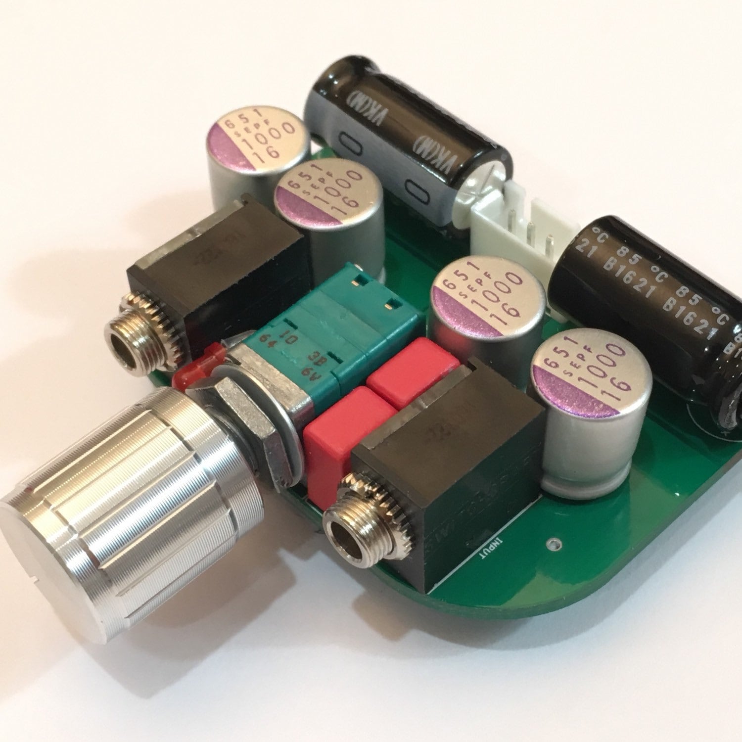
I took my time and had to wipe off a few pads because too much paste was applied. One of the steps that really helped was sticking the SMD components (while still in their packaged row) on a piece of blue tape to hold them in the order listed on the parts list. It kept me from misplacing components. When the board was completed, I was amazed with how fast the actual “soldering” went. With enough practice this method is much faster than soldering THT components.
Next up, Aksa Lender preamp SMT DB’s
@IAIMH
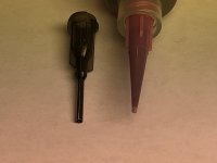
The pink tip I used came with a different tube of solder paste. The two nozzles that came with the MGChemicals paste that I used would never have worked, they were much too big. The pink nozzle hole is about 30% as big as the included syringe type nozzle.
I took my time and had to wipe off a few pads because too much paste was applied. One of the steps that really helped was sticking the SMD components (while still in their packaged row) on a piece of blue tape to hold them in the order listed on the parts list. It kept me from misplacing components. When the board was completed, I was amazed with how fast the actual “soldering” went. With enough practice this method is much faster than soldering THT components.
Next up, Aksa Lender preamp SMT DB’s
@IAIMH
The pink tip I used came with a different tube of solder paste. The two nozzles that came with the MGChemicals paste that I used would never have worked, they were much too big. The pink nozzle hole is about 30% as big as the included syringe type nozzle.
Attachments
Thanks for the kind words fellas
I took my time and had to wipe off a few pads because too much paste was applied. One of the steps that really helped was sticking the SMD components (while still in their packaged row) on a piece of blue tape to hold them in the order listed on the parts list. It kept me from misplacing components. When the board was completed, I was amazed with how fast the actual “soldering” went. With enough practice this method is much faster than soldering THT components.
Next up, Aksa Lender preamp SMT DB’s
@IAIMH
The pink tip I used came with a different tube of solder paste. The two nozzles that came with the MGChemicals paste that I used would never have worked, they were much too big. The pink nozzle hole is about 30% as big as the included syringe type nozzle.
I need to get some of those smaller nozzle tips. The one I have is a bit too large for smaller pads and can be a real pain to apply cleanly.
Hey Pcgab,
If you need a lead-free low temp paste the pink tip was included
No Clean Lead Free Low... No Clean Lead Free Low Temperature Solder Paste 15 Grams - - Amazon.com
If you need a lead-free low temp paste the pink tip was included
No Clean Lead Free Low... No Clean Lead Free Low Temperature Solder Paste 15 Grams - - Amazon.com
Thanks everyone. I ordered up a variety of the tapered tips. Brilliant. Maybe I can take up a side gig and learn to do henna tattoos. Can't imagine what they'd have to do with henna and hydroponics, but those seem to be tagged keywords.
I never thought to store it in the fridge after use. Noted with thanks. I don't use a ton of paste, so that's a great tip.
I never thought to store it in the fridge after use. Noted with thanks. I don't use a ton of paste, so that's a great tip.
Updated Design for 2SK209BL and ZXMN10A8 MOSFET
Hi Folks,
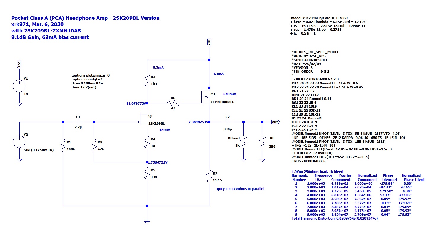
Due to the end of life of my favorite JFET, the BF862 and now, the end of the old MOSFET we used, it is time to update the design to some available options. The Toshiba 2SK209BL actually is working out really well. I am getting some nice performance with about 0.02%THD for 1.0Vpp into a 250ohm load.
Hi Folks,
Due to the end of life of my favorite JFET, the BF862 and now, the end of the old MOSFET we used, it is time to update the design to some available options. The Toshiba 2SK209BL actually is working out really well. I am getting some nice performance with about 0.02%THD for 1.0Vpp into a 250ohm load.
Attachments

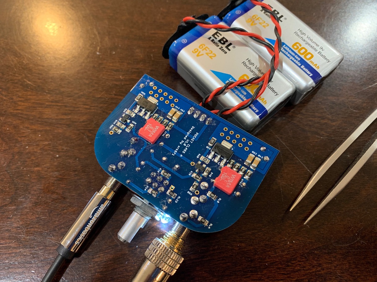
I just built a verification unit using the above resistor settings and 2SK209BL and ZXMN10A08GTA. For R3, I did not have a 1k3 on hand so used a 1k2 1210 resistor in its place. It resulted in a slightly higher bias current iof 72mA, but that's ok as I will be using them with lower impedance phones. I am using the 2200uF 16v Nichicon rail cap as the output cap, now bypassed with a 0.1uF 100v Wima MKS. The sound is excellent!

Attachments

Last edited:
I bought the 'PALO' 9V rechargeable batteries from Amazon and even after making sure they are fully charged, when I plug them into this amp, it doesn't turn on and the meter on the batteries show them as completely empty. The amp works fine with alkaline 9V batteries though. Is there anything specific to look for in buying rechargeables for this one?
These are the batteries I bought:
PALO 2-Pack USB 9V 650mAh Rechargeable Li-ion Battery with USB Cable for Keyboard Microphone Universal Remotes: Amazon.ca: Electronics
These are the batteries I bought:
PALO 2-Pack USB 9V 650mAh Rechargeable Li-ion Battery with USB Cable for Keyboard Microphone Universal Remotes: Amazon.ca: Electronics
Rechargeable batteries have a smart short circuit detector that cuts the battery out to prevent them from burning in case of a short. The sudden in rush of charging the capacitors fools the smart battery into thinking it is a short.
The solution is to quickly turn on/off with 3-5 clicks and each time the cap charges up enough until it doesn’t think it’s a short. This is a known issue and discussed earlier.
Be aware that the 650mAhr rating is based on the native 3.6v lithium ion cell. After DC-DC step up to 9v the capacity is 3.6v/9v x 650mAhr = 260mAhr. Not as high as the EBL batteries which are rated at 400mAhr at 8.2v. OTOH, these have a voltage regulated output and maintain 9v until they die.
Last edited:
I'm probably not building another one of these, but, what about values for 2SK209-GR? (following on from the discussion about BLs being unobtainable and using GRs for the Hakuin)
May help someone who is looking to build.
May help someone who is looking to build.
I just built a verification unit using the above resistor settings and 2SK209BL and ZXMN10A08GTA. For R3, I did not have a 1k3 on hand so used a 1k2 1210 resistor in its place. It resulted in a slightly higher bias current iof 72mA, but that's ok as I will be using them with lower impedance phones. I am using the 2200uF 16v Nichicon rail cap as the output cap, now bypassed with a 0.1uF 100v Wima MKS. The sound is excellent!
YOB:
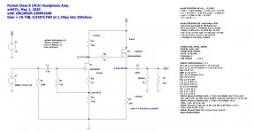
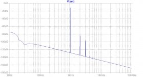
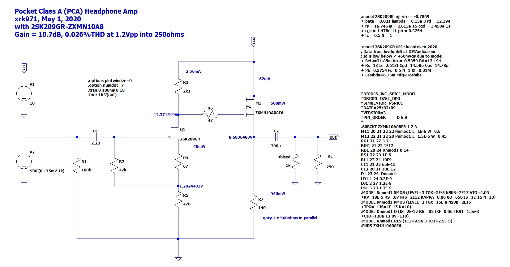
I just got a new LTspice model of the 2SK209GR from Keantoken. Here is what the latest simulation shows for a good circuit with the 2SK209GR and ZXMN10GTA. This will drive 250ohm cans to 1.2Vpp with 10.7dB gain and 0.026%THD.

This is for 1.2Vpp into 250ohms:
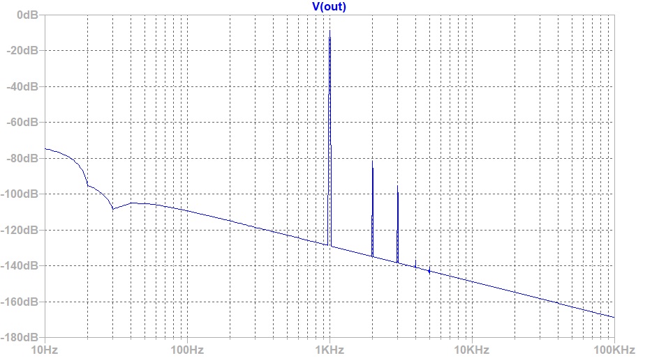
I just got a new LTspice model of the 2SK209GR from Keantoken. Here is what the latest simulation shows for a good circuit with the 2SK209GR and ZXMN10GTA. This will drive 250ohm cans to 1.2Vpp with 10.7dB gain and 0.026%THD.
This is for 1.2Vpp into 250ohms:
Attachments
An update to my previous post about batteries:
No matter how many times or how quickly I cycled the power with the 650mAH "PALO" batteries, the short protection would trigger immediately so they just would not work. I ordered the black 600mAH PALO 9V batteries and they work as do the 600mAH EBL batteries in XKR971's pictures.
So word of warning - do not buy the 650mAH PALO batteries (white case) with the USB connector and power indicator leds for use with this headamp.
I have sort of neglected to update the BOM since the BF862 and ZVN4396 have been discontinued.
Please use this schematic:
Here is what I think is the BOM that goes with the 2SK209GR and ZXMN10:
Please use this schematic:
Here is what I think is the BOM that goes with the 2SK209GR and ZXMN10:
All resistors 0805 package, metal thick film, 1% on specified parts, else 5%. Yageo 1% 0805 SMT from Digikey are $0.77 for 100
R1 100k (5%)
R2 47k (1%)
R3 1k (1%) ** use 2k2 for 2SK209GR **
R4 33R (1%) ** use 67R for 2SK209GR **
R5 270R (1%) ** use 470R for 2 SK209GR **
R6 47R (5%)
R7_1 470R (1%)
R7_2 470R (1%)
R7_3 470R (1%)
R7_4 470R (1%)
RL 270R (5%) User select (optional, use for higher current draw on amp)
RLED 12k or 15k (5%) Current limit for LED, 15k or value according to supply voltage
C1 Input cap 5mm pitch up to 5.5mm wide (Wima 2.2uF MKS2B042201F00JSSD)
C2_1 Output cap 3.5mm pitch, 8 dia (390uF 20v Panasonic OSCON 20SEPF390M) or Nichicon AK 470uF if you can fit it Edit: I highly recommend a 1000uF 16v OSCON here for low impedance phones.
C2_2 Output cap 5mm pitch, up to 9mm wide (Wima 1uF MKS2C041001F00KSSD) Edit: I highly recommend a second 1000uF 16v OSCON here, if you have 30ohm or lower phones, and place Wima on SMT side.
C3 Rail cap 100uF 3.5mm pitch, diameter whatever you can fit in the tin (100uF 20v Panasonic OSCON 20SEP100MX) - or highly recommended Nichicon 2200uF 16v - lay on its side
C4 Rail cap 100nF 1206 package (50v X7R)
C5 Additional 100nF rail cap 1206 package (50v X7R)
Q1 BF862 (771-BF862-T/R) *** if BF862 not available Use 2SK209GR ***
M1 ZVN4306GTA *** if ZVN4306 not available, a great alternative is ZXMN10A08GTA ***
Switchcraft 3.5mm stereo jacks x2 (35RAPC4BV4)
Alps 10kOhm stereo pot with power switch (RK0971221Z05)
3mm round LED (red or green)
4-pin 2.54mm pitch power connector (see post #44)
With a bit more free time than usual due to you-know-what I've started building another one of these with the 2SK209GR + ZXMN10.
How'd you manage to fit 2x 1000u OSCON on the output? It doesn't seem to want to fit for me - not enough clearance to have them side by side.
Also, not sure if this thread is still getting much interest, but an update for the BOM - for the rail cap, if lying it on its side, you can easily fit either a 2200u 25V EEU-HD (Panasonic), or if happy to use 16V, a 3300u EEU-HD will fit as well (12.5x20mm).
I've also fit a 3300u 25V before, laying it pointing "forward" (toward the pot and sockets) but that required creative wiring for the output caps.
R7 on the BOM should be revised to 560R, assuming the diagram is the correct one.
Hi YOB,
You have to put a dogleg bend on the pins of one of the 1000uF SEPFs. It fits fine:
https://www.diyaudio.com/forums/group-buys/302859-xrk971-pocket-class-headamp-gb-58.html#post5058562
Regarding R5, for 2SK209GR I used 470R not 540R, per the schematic above.
Glad to see you are getting back into this amp. It still is one of my favorite headphone amps, despite having much bigger and fancier ones, this one always puts a smile on my face when I listen.
Built it up and took some measurements - I built at per the spice schematic with 560R x4, used 68R on R4 but it was running way too hot - 10.8V across R7 / 77mA.
I had to take R4 down to 24R to get anything resembling the spice sim. Voltage across R7 settles somewhere between 9.25-9.35V with about 0.05V difference between the channels. Voltage at R4-R5 junction was 1.20/1.21V and R3-R4 was 12.37/12.38V
Not sure if I just got hot running fets or if it's something to do with the models used in the sim, just thought I'd let you know.
It may have to do with your particular 2SK270. It almost sounds like you have a BL rated one, in which case the setpoints are different. If you are needing to adjust bias current / DC at the output cap try changing R3. Larger value is higher voltage at Source of the mosfet. Problem with making R4 too low is the H2 will increase food much.
- Home
- Group Buys
- xrk971 Pocket Class A Headamp GB