The current is a function of the individual MOSFET gain and very similar to the ZVN4306. I measured about 24 of them in-situ and there were variations but for the most part, had a bit less current flow for same resistor network. I ended up at 54mA which is fine. My amp was running kind of high at 70mA before but that because of a “hot” ZVN4306. You battery usage will track with current and 54mA is good for about 4.5hrs to 5hrs.
Hm, I'll have to go review my old notes then. Thanks for the update. You mentioned that lower impedance headphones might possibly be driven better. What is the parameter that affects that? Is that a function of current as well (thinking that low impedance, low sensitivity phones = high current required to drive to desired level)
you can test in circuit if you want, just measure for voltage across the parallel resistors (from memory ... read through the posts here to be sure), dont solder the DUT in. just hold it down with something nonconductive (I used back end of pencil).
just pick from the same reel/strip and should be close enough if you don't measure (I think X said this as well)
Order 2 (or more) boards in case of problems!!
just pick from the same reel/strip and should be close enough if you don't measure (I think X said this as well)
Order 2 (or more) boards in case of problems!!
Last edited:
I'm a newbie when it comes to DIY. I only have a normal soldering iron and don't have a SMD workstation. I don't have an oscilloscope. SO, would you recommend this board for me ?
Yes, I would. If I could build this, you can also. All you need is a soldering iron with a fine tip, 0.6mm solder wire and a digital multimeter. Helping hands and a magnifying lamp helps. I use 3x reading glasses. Watch a few YouTube videos on smd soldering, then you should be good to go.
This is a great sounding amp and a very nice project for a newbie – low parts count, low cost components, but great rewards! Lots of help available here if you need.
All above tips on SMD soldering are great. Good magnifier goggles are needed if eyes are old (45+yrs), good stainless steel tweezers, small dia rosin core solder and small iron tip. Put a small dab of solder on one pad, place part and apply pressure on top with tweezer while touching end with solder bump. Once it melts the part presses down flush with board. Now do same on other end. There should be a smooth fillet of solder to avoid cold solder junction. Cold solder joints are main reason (98% of time) someone can’t get this amp to work first time. Watch YouTube videos.
Take ESD (static sensitive parts) precautions when handling JFETs or MOSFETs. Discharge body on nearby grounded object or wear grounded wrist straps. Don’t wear wool or polyester clothes when assembling. That’s the other 2% reason whey the amp build sometimes doesn’t work.
Alternatively, use solder paste hypo needle dispenser and put paste on pads, place parts on paste and put PCB with paste and parts on old aluminum frypan and heat on hot plate until solder liquifies and parts self align via surface tension - may need adjustment manually with tweezer if they don’t sit right.
Remove from heat and cool pan on wet paper towel to reduce time board cools down.
You don’t need to match for normal use - just pick two consecutive JFETs or MOSFETs from same strip and will be good enough for most. But if you want same bias current to match and be the same for best channel balance, then match them with a test jig (the board with resistors and power but don’t solder). You can also buy them prematched from my shop.
There are very few parts and it’s easy to solder - literally hundreds of people have successfully done this project. All report superb sound.
Note that you can also buy a SMT matched FET and prepopulated and tested board. Just install all through hole parts yourself.
Finally, if a small pocket amp is not primary need, make the desktop version of this amp using through hole parts (except for JFET). Option exists to use 2SK170 TH JFET here (solder pads are provided). It allows running higher 125mA bias current and higher voltage to drive your 32ohm headphones with ease. Depending on how sensitive your EB2 headphones are, the pocket Class A may or may not drive them well. 98dB/mW is about the lowest I would go for 30ohm headphones. With the desktop version you can have lower impedance and lower sensitivity phones, plus easy TH soldering.
xrk971 Desktop Class A (DCA) Headphone Amp
Last edited:
A New Spin on this Topology
Well folks, it’s been a while since this amp has been out and by all accounts, the sound quality it is capable of has been very well received. However, I have been trying to get a bit more performance from this amp for a lower impedance headphone, plus I have tuned the harmonic distortion profile to have much more dominant second order relative to the third order and higher orders for a much more improved sweetness of sound. I also have another motive - to get the bias current in the input JFET down to circa 100uA (it’s about 7mA now). That’s a huge change and the need for a 100uA bias current will provide the opportunity to test this amp with a new input device that I am keeping a secret for now (testing still needed). However, in adjusting the circuit for this very low bias across the BF862, some benefits came out: the gain is increased and this improves the dynamics of the presentation, the sound is more engaging and pleasingly natural, the power consumption is now less since much lower dissipation across the JFET.
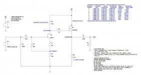
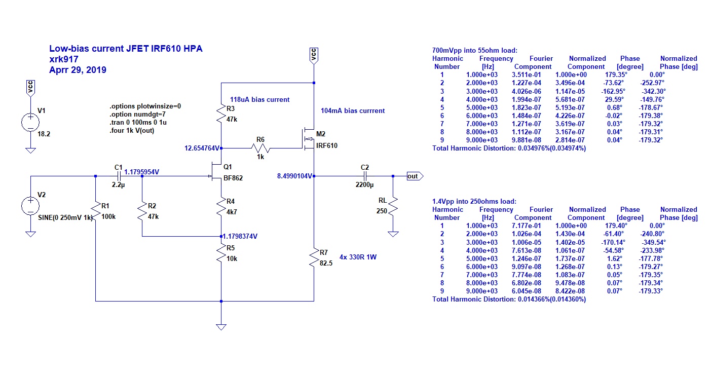
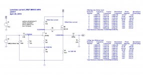
Here is the revised schematic. As you can see, the DC setpoint resistors are significantly larger. Predicted bias current across the JFET is now about 117uA:
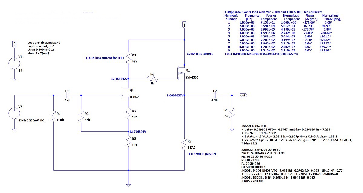
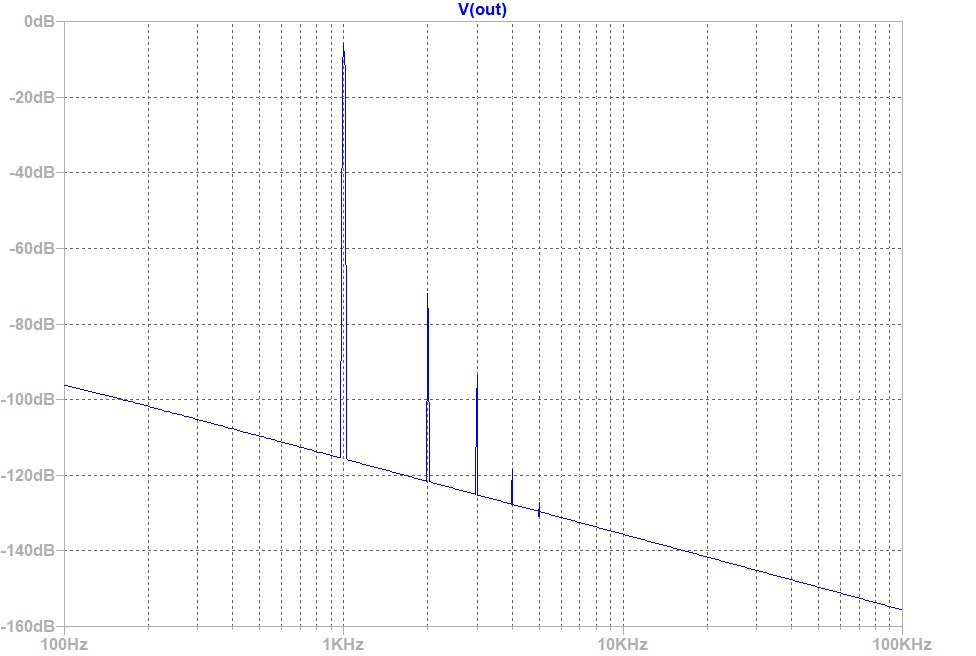
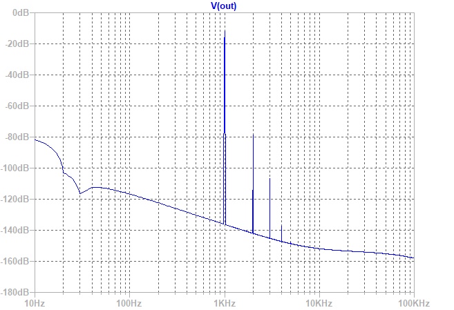
Here is the predicted harmonic distortion profile for 1.4Vpp into a 55ohm load:
So I have built this and am listening to it now - it’s very nice to listen to indeed. The dynamics and range of sound from very soft to very loud is huge. A new amp in sound basically. If you are curious, give it a try. You can either remove and reinstall the new SMT resistors or make a new one to have two amps. Both sound great but this new one sounds even sweeter.
Well folks, it’s been a while since this amp has been out and by all accounts, the sound quality it is capable of has been very well received. However, I have been trying to get a bit more performance from this amp for a lower impedance headphone, plus I have tuned the harmonic distortion profile to have much more dominant second order relative to the third order and higher orders for a much more improved sweetness of sound. I also have another motive - to get the bias current in the input JFET down to circa 100uA (it’s about 7mA now). That’s a huge change and the need for a 100uA bias current will provide the opportunity to test this amp with a new input device that I am keeping a secret for now (testing still needed). However, in adjusting the circuit for this very low bias across the BF862, some benefits came out: the gain is increased and this improves the dynamics of the presentation, the sound is more engaging and pleasingly natural, the power consumption is now less since much lower dissipation across the JFET.
Here is the revised schematic. As you can see, the DC setpoint resistors are significantly larger. Predicted bias current across the JFET is now about 117uA:
Here is the predicted harmonic distortion profile for 1.4Vpp into a 55ohm load:
So I have built this and am listening to it now - it’s very nice to listen to indeed. The dynamics and range of sound from very soft to very loud is huge. A new amp in sound basically. If you are curious, give it a try. You can either remove and reinstall the new SMT resistors or make a new one to have two amps. Both sound great but this new one sounds even sweeter.
Attachments
Last edited:
Low bias JFET DCA
Here is the schematic for the low bias currrent DCA HPA. 118uA bias current for BF82 and 104mA for IRF610:
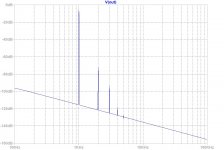
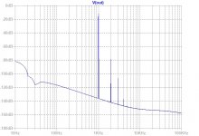
Predicted FFT for 1.4Vpp into 250ohms (THD is about 0.01%):
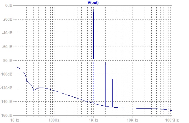
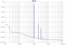
Predicted FFT for 700mVpp into 55ohms (THD is about 0.03%):
Here is the schematic for the low bias currrent DCA HPA. 118uA bias current for BF82 and 104mA for IRF610:
Predicted FFT for 1.4Vpp into 250ohms (THD is about 0.01%):
Predicted FFT for 700mVpp into 55ohms (THD is about 0.03%):
Attachments
Last edited:
Q1 can be replaced with J112?
https://www.tme.eu/Document/2ab8d7a6d6d8a209f9d7deeb52763e9f/J111.pdf
https://www.tme.eu/Document/2ab8d7a6d6d8a209f9d7deeb52763e9f/J111.pdf
For example, AliExpress - look for code stamped 2AW. Price should not be too cheap.
Online Shop 10pcs/lot BF862 Stamp 2AW SOT-23 original authentic | Aliexpress Mobile
Online Shop 40pcs/lot BF862 Stamp 2AW SOT-23 new original | Aliexpress Mobile
If they send you one not stamped 2AW, file complaint and get a refund. All of ones I have received lately are genuine (checked with JFET Idss matching rig).
I like Aliexpress, but if you want a supplier closer to home:I never bought electronic components on that site but I'll make a try.
Thank you.
bf862 jfet | eBay
- Home
- Group Buys
- xrk971 Pocket Class A Headamp GB