I did go look at the plots for the IRF610 and sure enough, its transconductance is considerably lower than the FET in the current schematic (ZVN4306). Higher transconductance translates to real-world benefits - lower distortion and also lower output impedance. An open loop amp has no reduction of Zout due to loop feedback so transconductance is more of an issue without global feedback being applied.
I've attached the IRF610's relevant plot - the slope of the lower curve gives the gm (transconductance) - for a typical bias current of 30-60mA the gm is in the region of 150mS which gives an output impedance around 6ohms.
I am looking at both data sheets but cannot find Gm (transcondustance), I only found Gfs (forward transconductance) and for stock mosfet is 0.7S min and IRF610 is 0.8S min.
Ability to dissipate heat since a local heatsink can be attached and lower transconductance.
I can only find "forward transconductance" on each data sheet, is this what you are referring to? IRF610 is actually 0.1S higher, but their test conditions differ, so is calculation required to fairly compare?
Hi X,
I just switched to a 18V 60W medical grade switching DC power supply and replaced mosfets with NTE2378
here are my new measurements:
channel B:
R7: 7.79
MOSFET GDS: 10.93, 18.02, 7.8
JFET GDS: 1.91, 10.94, 2.1
R3: 7.1
channel A:
R7: 7.53
MOSFET GDS: 10.64, 18.02, 7.56
JFET GDS: 1.99, 2.25, 10.63
R3: 7.39
PS btw, i just realized my R4 values are both 33R (i think i read somewhere you recommend starting with 47R for R4, but from one of the pre-made mouser shopping carts on post 1, 33R was listed as R4)
Last edited:
Hi X,
I just switched to a 18V 60W medical grade switching DC power supply and replaced mosfets with NTE2378
here are my new measurements:
channel B:
R7: 7.79
MOSFET GDS: 10.93, 18.02, 7.8
JFET GDS: 1.91, 10.94, 2.1
R3: 7.1
channel A:
R7: 7.53
MOSFET GDS: 10.64, 18.02, 7.56
JFET GDS: 1.99, 2.25, 10.63
R3: 7.39
PS btw, i just realized my R4 values are both 33R (i think i read somewhere you recommend starting with 47R for R4, but from one of the pre-made mouser shopping carts on post 1, 33R was listed as R4)
View attachment 621337
View attachment 621338
Nice work. That mosfet looks like us working and you are getting 65mA bias and your output voltage is basically balanced at the halfway point. How does it sound? If you make R4 larger, say 47R you might get 75mA or 80mA bias. You will need a heatsink on those MOSFETs then.
Watch out for running too much current through R7's. Above 65mA it's exceeding 500mW. You can try switching over to the desktop amp values and see if this mosfet works similarly to an IRF610.
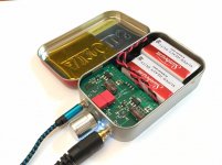
The modification took longer than I anticipated (the S solder pad of mosfet B broke when I was removing stock mosfet, any tip to easily de-solder stock mosfet?) so I was already running late to pick up my toddler from the daycare when I completed my work. I did a quick listen and here are my 60 sec listening impression
1. Channels appear balanced
2. Channels appear to be clean sounding, but I wasn't listening for noise
3. I used Walnut V2 DAP playing WAV files, using line out into PCA, I feel it sounds better than Walnut directly out of headphone out
4. FWIW Walnut V2 vs Fiio X3ii or Xduoo X3, maybe not beat them, but close enough to promote discussions on HeadFi
Keep in mind this is very quick listening impressions and I was in a hurry to get out the door
Question, for my next step, would cap rolling yield better sound improvement or going with the full desktop variant modification?
Last edited:
comparing data sheets, ZVN4306G also differ from IRF610 as follows:
Vds: 60V vs 200V
Vgs: same
Id: 2.1A vs 3.3A
Idm: 15A vs 10A
so which spec makes IRF610 the better mosfet suitable for a desktop variant build? is it the higher Vds or Id?
None of those specs are particularly relevant to this application since its low voltage (a 20V FET would probably still do fine), low current (a 200mA FET also will most likely be sufficient). As X says, his choice of the IRF610 is to achieve lower thermal impedance - translated means less temperature rise with the same power dissipation.
'Forward transconductance' is the same as my term 'transconductance' - notice its heavily dependent on drain current and normally the drain currents specified in the DSs are way, way above the currents encountered in operation as a headphone amp. Hence the 'headline' figures for gm are mostly useless in this application.
To answer your later question, yes the test conditions (Id) are very important when comparing gm figures. IRF is specified at 2A, ZVN at 3A - both are far, far from the operating point here so to uncover the value of gm at say 50mA requires doing a bit of detective work from the published plots. The figures are also minimums, giving no indication of what the typical might be.
I used Walnut V2 DAP playing WAV files, using line out into PCA, I feel it sounds better than Walnut directly out of headphone out
This is to be expected. A SE Class A amp will drive a headphone better than the stock opamp being used by the DAP's headphone out. You can even try this as a preamp from your DAC to your power amp driving your big speakers: it will sound better, every time.
This is to be expected. A SE Class A amp will drive a headphone better than the stock opamp being used by the DAP's headphone out. You can even try this as a preamp from your DAC to your power amp driving your big speakers: it will sound better, every time.
I am not familiar with preamp usage, and wouldn't that be double amping?
You can even try this as a preamp from your DAC to your power amp driving your big speakers: it will sound better, every time.
In my experience headamps such as these sound better when used as 'preamps' into poweramps because they have a higher input impedance than typical poweramps. Plus the JFET input helps a lot with RF rejection, DACs are rather noisy in ultrasonics typically.
No, it's not not double amping. People use preamps all the time as a volume controller or source selector in one. Some power amps like certain Class A amps have very low gain of 15dB and need a preamp to get to 27dB or so in order to be able to hit clipping levels. But if you have a plain power amp with no volume control, and you feed your CD player RCA out tonyiur pocket amp as a preamp, you now have a volume controller that can drive multiple power amps with a fan-out as long as combined impedance of all amp inputs is >60ohms you are good. Most amp inputs are 47k to 10k.
This will imbue your power amp with a SE Class A harmonic signature.
This will imbue your power amp with a SE Class A harmonic signature.
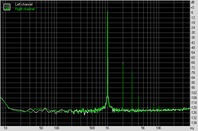
Another NHB going out to Singapore. This one is tuned to dig deep with LCD-2. Dual 1000uF 16v OSCONs + 10uF 35v Silmic II's on outputs, and 10uF 35v Silmic II's + 1uF 63v Wima MKS on inputs.

Measured FFT:
Measured FFT:
Attachments

Last edited:
In case anyone is looking for a budget priced but great sounding headphone to go with my amp, I can highly recommend the SM-OB1 from Status Audio (I don't get anything from this recommendation, if you are wondering). I just like how it sounds. And a recent price drop on Amazon to $55 makes it a steal. I just got another set for backup or for converting to balanced drive (perfect for it as it has two wires - one for each side). They are extremely sensitive above their rated 96dB and the bass has a visceral punch. Nice mids and highs, although the highs on my DT880's are "more refined", for all around listening, I think they are great. The (Innerfidelity measured) 70ohm impedance is a nice match for the Pocket Class A.
https://www.innerfidelity.com/images/StatusSMOB1.pdf
Same company is also offering a 50% off web coupon code for their foldable over-ear HD-1 model. Code is in attachment and only works from the manufacturer's wbsite. I don't know how these will sound but the price is right. They say it has a V shape enhanced bass/treble response so probably good for commuting or hip hop etc.
Attachments
Last edited:
Silicon Harmony casework is a PITA. A 24mm Forstner bit goes through 8mm thick aluminum plate well (for headphone jack).
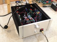
It's mostly together and listening and checking temperatures. Heatsink is reaching about 50 deg C at the middle where the MOSFETs are located. Sound is still great. Very quiet, no noise or hum. Super powerful sound.
It's mostly together and listening and checking temperatures. Heatsink is reaching about 50 deg C at the middle where the MOSFETs are located. Sound is still great. Very quiet, no noise or hum. Super powerful sound.
Attachments
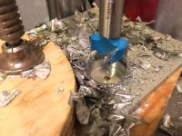
Thanks, Prasi! You did a beautiful job on the layout for this board. Looks and sounds great. I didn't know what a PITA casework is until I had to hog-out a big hole in aluminum. Noisy, messy, time consuming. But it had to be done. Soldering is so much more fun ")
I am always amazed when I plug in a 112dB/mW sensitive headphone into an amp that is plugged into the wall mains and hear no hiss or hum or noise of any sort. Headphone amp designs have to be absolutely silent when no signal playing. It's a lot harder that it seems. This is the same as measuring 0.0mV AC volts on the outputs with the Fluke.
I am always amazed when I plug in a 112dB/mW sensitive headphone into an amp that is plugged into the wall mains and hear no hiss or hum or noise of any sort. Headphone amp designs have to be absolutely silent when no signal playing. It's a lot harder that it seems. This is the same as measuring 0.0mV AC volts on the outputs with the Fluke.
- Home
- Group Buys
- xrk971 Pocket Class A Headamp GB