I was under the impression Kapton's raison d'etre was as a heat and electrical insulator, so in my head some other solution is probably more performant...but I don't know very much so I could be dead wrong.
I'm also curious what advantages raptorlightning's load sharing board offers over the dirt cheap and seemingly ubiquitous TP4056 module? 5PCS Micro USB 5V 1A 18650 TP4056 Lithium Battery Charger Charging Board New | eBay
To me, they look like they perform the same function and I was under the impression the draw of the PCA is <1A, but once again, I know very little.
If you look at the PCB of the TP4056 modules you'll see that the output of the 4056 is connected to both the battery and the output of the board. This means that if you have the amp on and plugged in, the battery may never actually charge or finish charging. The load share board ensures that there are two separate circuits when 5V is applied to the USB connector - one for charging the battery and another, separate pass-through for powering the amplifier section. This website goes into more detail on how the circuit functions:
A Lithium Battery Charger with Load Sharing – Zak's Electronics Blog ~*
Well, there's good news and bad news with my hum issue.
I got rid of the hum by replacing the second cap in my six-cap bank with a couple of
2.2R/2W resistors. Sort of a CRCCCC if you will. voltage dropped by half a volt, to 17.3.
Then I decided to replace R4 back to a 51R from the 42.2R I had, and now I have a hiss
in the left channel. I'm thinking I may have done something to Q1A possibly. It still plays music though, just with hiss as accompaniment.


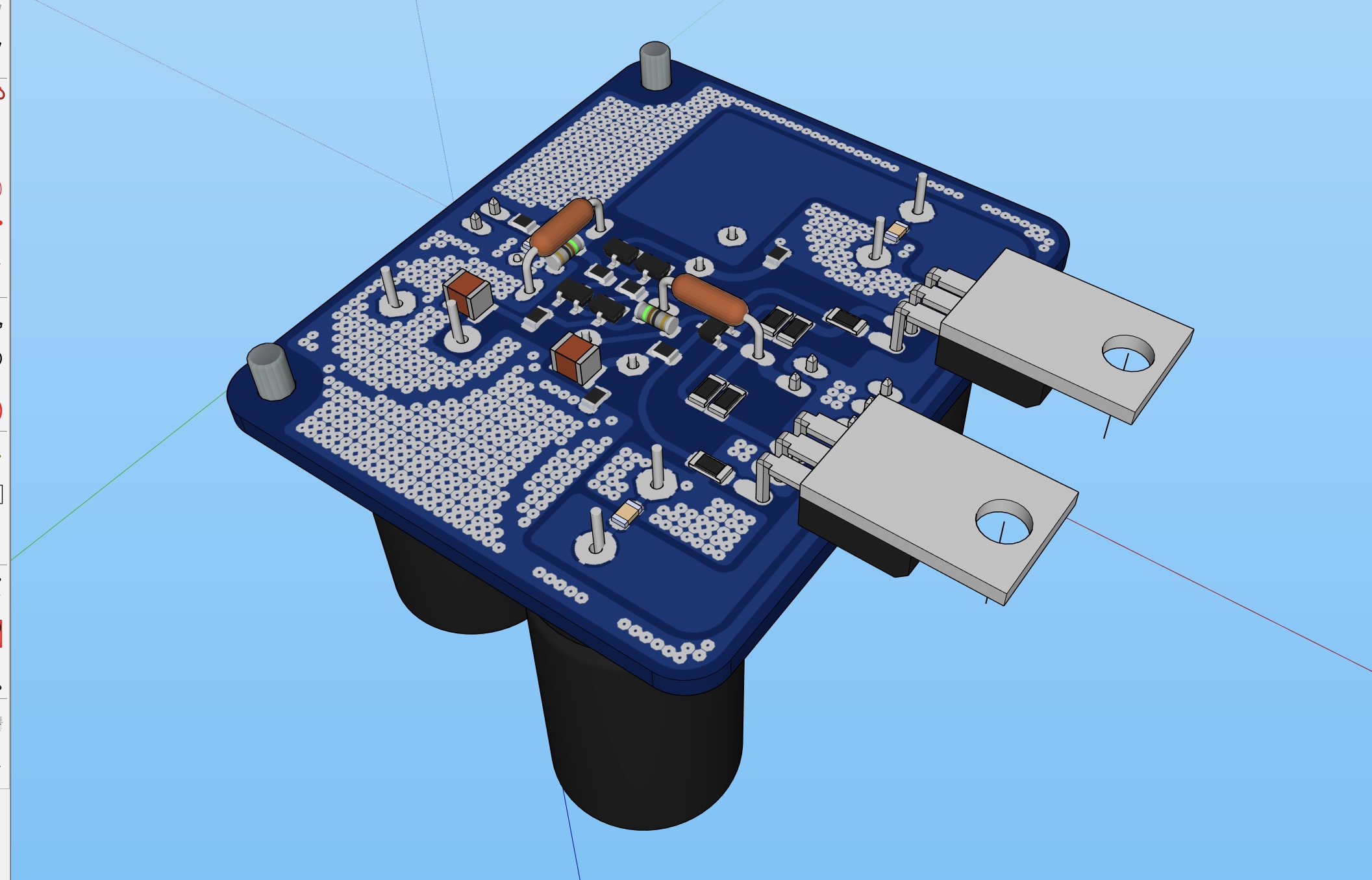
Just wanted to let you all know about an exciting new DC coupled headphone amp design that I am working on. It’s simple but with astonishingly good performance. Very powerful, dynamic and open sound. Not good for capnfollingbas there are no caps! DC offset is under 5mV and auto regulating via topology. Uses same BF862 JFETs (4 of them on front end) and almost any P channel MOSFET on output stage. Layout by JPS64 so you know will be good.
My hand etched prototype sounds very good - measures about 0.005%THD and all H2 but this is probably due to a cheap resistor that is adding the distortion. Simulations show sub PPM THD. I predict that with proper PCB and quality parts like Dale resistors and metal thin film resistors vs metal thick film resistors on critical audio path, THD will drop. I only had cheap steel terminal Chinese resistor on hand (2.7R 1/4w 1% metal thin film) I think the limitation is the steel leads and translation to metal film interface. Or it may be the 2SJ313’s vs IRF9610 which I used since Inhad on hand.
Anyhow, check it out if interested. Should be a quick build and no expensive parts.
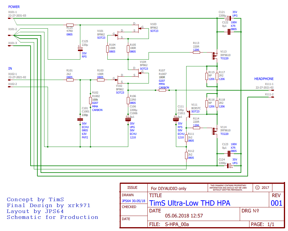
Here is simulation schematic:
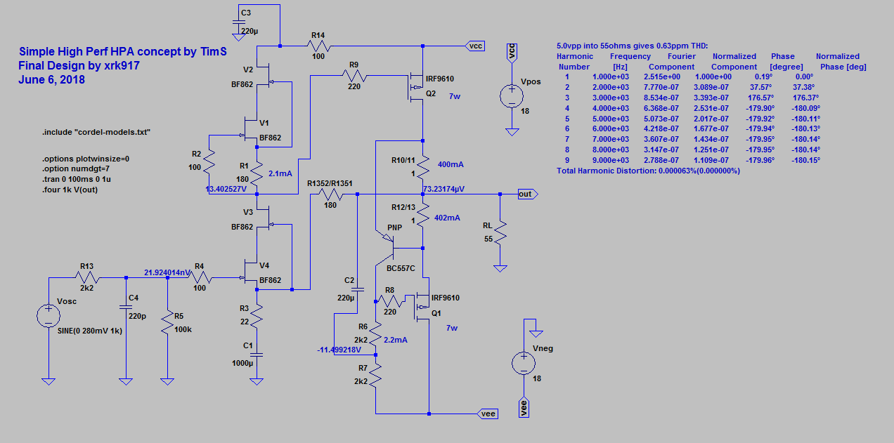
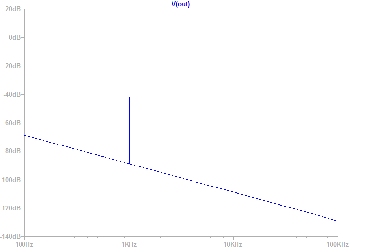
Here is predicted FFT for 5vpp into 55ohm load at optimal design bias of 400mA (essentially disorion free):
Thread here:
Simple High Performance DC Coupled Class A HPA with sub PPM THD
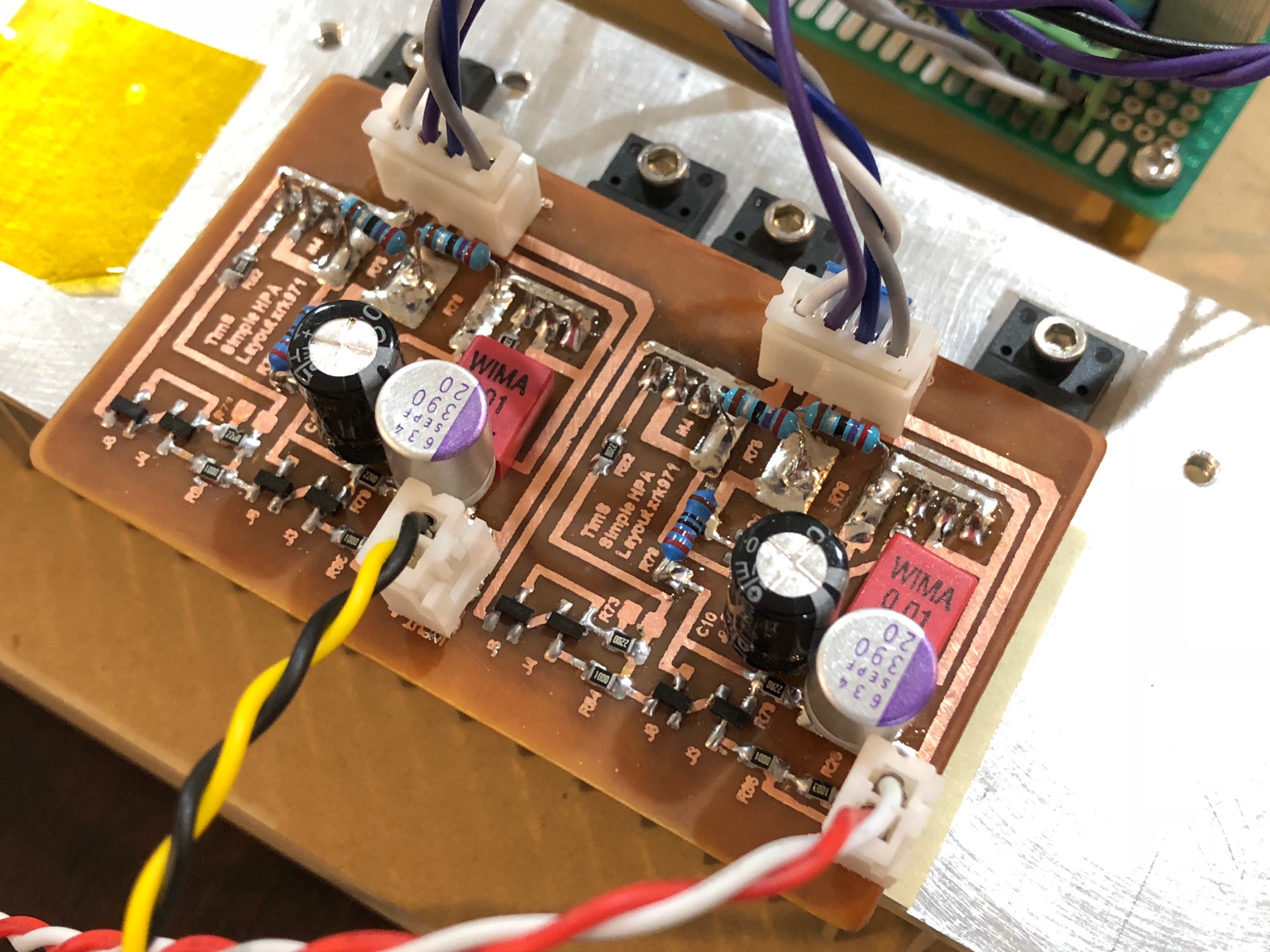
Prototype:
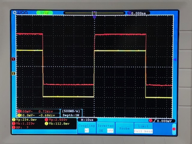
2.5vpp 10kHz square wave measurement:
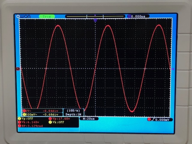
For 115mA bias case and 15v rails makes 17.6vpp before clipping into 42ohms. That’s about 1w:
My hand etched prototype sounds very good - measures about 0.005%THD and all H2 but this is probably due to a cheap resistor that is adding the distortion. Simulations show sub PPM THD. I predict that with proper PCB and quality parts like Dale resistors and metal thin film resistors vs metal thick film resistors on critical audio path, THD will drop. I only had cheap steel terminal Chinese resistor on hand (2.7R 1/4w 1% metal thin film) I think the limitation is the steel leads and translation to metal film interface. Or it may be the 2SJ313’s vs IRF9610 which I used since Inhad on hand.
Anyhow, check it out if interested. Should be a quick build and no expensive parts.
Here is simulation schematic:
Here is predicted FFT for 5vpp into 55ohm load at optimal design bias of 400mA (essentially disorion free):
Thread here:
Simple High Performance DC Coupled Class A HPA with sub PPM THD
Prototype:
2.5vpp 10kHz square wave measurement:
For 115mA bias case and 15v rails makes 17.6vpp before clipping into 42ohms. That’s about 1w:
Last edited:
Just wanted to let you all know about an exciting new DC coupled headphone amp design that I am working on. It’s simple but with astonishingly good performance. Very powerful, dynamic and open sound. Not good for capnfollingbas there are no caps! DC offset is under 5mV and auto regulating via topology. Uses same BF862 JFETs (4 of them on front end) and almost any P channel MOSFET on output stage. Layout by JPS64 so you know will be good.
...
For 115mA bias case and 15v rails makes 17.6vpp before clipping into 42ohms. That’s about 1w:
I have had my head buried in a RPi DAC project lately and haven't jumped on the DCA build due to lack of time and funds. But had to jump in to say THIS looks awesome. After my cap-rolling extravaganza in the pocket amp, I concluded that no electrolytic cap is perfectly transparent, and I've been longing to hear a Class A, direct coupled amp ever since. Looks like that time may be approaching.

YOB's new DCA looks killer BTW. And love the tiger tin too!
I have had my head buried in a RPi DAC project lately and haven't jumped on the DCA build due to lack of time and funds. But had to jump in to say THIS looks awesome. After my cap-rolling extravaganza in the pocket amp, I concluded that no electrolytic cap is perfectly transparent, and I've been longing to hear a Class A, direct coupled amp ever since. Looks like that time may be approaching.
YOB's new DCA looks killer BTW. And love the tiger tin too!
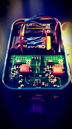
Good to see more interest in this amp. I boxed up my prototype:
GB thread here:
Simple High Performance DC Coupled Class A HPA with sub PPM THD
If you look at the PCB of the TP4056 modules you'll see that the output of the 4056 is connected to both the battery and the output of the board.
A Lithium Battery Charger with Load Sharing – Zak's Electronics Blog ~*
there are many variants of the tp4056 modules. some just have a tp4056 and common +/- for charge and load, and some also have 2 additional ICs and separate terminals for charge and load. the latter are advertised as being able to charge and discharge simultaneously.
my shipment unfortunately rolled badly with customs and still isn't here almost 2 months later, so i modified a phone battery charger to have another set of terminals and am using that in the meantime.
my capmx also had shipping troubles, with oshpark's delivery from fab being delayed, and that still isn't here either. they refunded the $3 order for the delay. i am using a 1% 5W 47ohm resistor to boot the board in the meantime - i seen previous comments of people getting away with 1.5ohm but i tried everything from 1ohm to 20ohm and had no luck. think i'm only getting like 14 volts at the amp with the boost board maxed out.
Last edited by a moderator:
The MT3608 DC step up should make up to 24v no problem. Be careful with max current though. Good idea to have at least 4.7R resistor to limit current until cap Mx is in place as these MT3608 burst into flames when you adjust voltage and it hits max current. I have burned out at least 10 in a blaze of fiery glory.
And love the tiger tin too!
Thank you!

Just wanted to let you all know about an exciting new DC coupled headphone amp design that I am working on. It’s simple but with astonishingly good performance. Very powerful, dynamic and open sound. Not good for capnfollingbas there are no caps! DC offset is under 5mV and auto regulating via topology. Uses same BF862 JFETs (4 of them on front end) and almost any P channel MOSFET on output stage. Layout by JPS64 so you know will be good.
My hand etched prototype sounds very good - measures about 0.005%THD and all H2 but this is probably due to a cheap resistor that is adding the distortion. Simulations show sub PPM THD. I predict that with proper PCB and quality parts like Dale resistors and metal thin film resistors vs metal thick film resistors on critical audio path, THD will drop. I only had cheap steel terminal Chinese resistor on hand (2.7R 1/4w 1% metal thin film) I think the limitation is the steel leads and translation to metal film interface. Or it may be the 2SJ313’s vs IRF9610 which I used since Inhad on hand.
Anyhow, check it out if interested. Should be a quick build and no expensive parts.
Here is simulation schematic:
Here is predicted FFT for 5vpp into 55ohm load at optimal design bias of 400mA (essentially disorion free):
Thread here:
Simple High Performance DC Coupled Class A HPA with sub PPM THD
Prototype:
2.5vpp 10kHz square wave measurement:
For 115mA bias case and 15v rails makes 17.6vpp before clipping into 42ohms. That’s about 1w:
Hi Xrk971 ,
Its not fair .. by the we think to proceed on one amp/preamp you r coming up with something new .. being lazy , so far I only reached to the point of ordering few bf862 jfets .. yet to decide which one start with ..
by the we think to proceed on one amp/preamp you r coming up with something new
This one was by TimS, I only built it.
If you are undecided, take the Aksa Lender pre - it is a thoroughly tested, tried and true design with an inexpensive single rail design that is low noise like a battery. It Also sounds great and can drive headphones (with mod as HPA) to very loud low distortion levels with no fear of DC offset damaging phones.
it's a very different amplifier than my other ones - being DC coupled, you need to be careful with making sure input source has no DC, and your headphone doesn't get DC. The amp is pretty benign with turn on pops or clicks. I have tested turning on/off quickly and no harm done.
Curious why the low impedance BOM specifies thick film resistors but the BOM in the OP specifies thin film?
I mistakenly thought the parts I had were thin film, when in fact they were thick film. You can use thin film, they just cost more and perhaps will deliver a bit less distortion if you replace the qnty 4 x 460R resistors for R7 where there is a large amount of power dissipated.
But it will be a minor 0.004% THD change (on the nominal the 0.05% THD).
AP APx585 HDMI Analyzer or what are you using to measure thd,
you got some really expensive equipment to measure resistor noise.
Sound cards are are somewhat useless, at that degree of resistor noise measurement.
But you know the resistor noise is below soundcard computer noise.
They can give some indication for sure and good for students about since 1988.
How short are your wires to measure resistor noise.
If your still using the arta box there's way to much noise. Zener big Resistor bla bla. unless your just and so are many ic in soundcard.
Many use sound cards wrong to get better measurement results.
Good thing if the resistors are the reason I think you got something else going on.
Have fun.
Sound cards are are somewhat useless, at that degree of resistor noise measurement.
Not measuring resistor directly, but its effect on amplifier distortion at the load resistor being driven with 20vpp.
I just noted difference in my Aksa Lender preamp when switching between thick film and thin film feedback resistor. One part change. Measurable difference and my setup is Focusrite 2i4. THD+N is spec'd at 0.002% so whatever the MOx resistor did, it was greater. Noise floor as you can see, is at -130dB.
Here is preamp with thick film resistor (in qnty 4 series/parallel array to reduce effects of heating) for global feedback (exposed to full AC output swing) - gets 0.0026% THD:
Here is the same for resistor with metal thin film (axial) - gets 0.0023% THD and change in harmonic profile as well:
Seems like a measurable and obvious difference in character of distortion.
Last edited:
- Home
- Group Buys
- xrk971 Pocket Class A Headamp GB