When you hold them in your hand side by side you will see difference in the quality. I tried buying “similar” looking ones too from Aliexpress. Ok for a cheap prototype but I would never use it for one I sell. Even the knurled little ring nut is nicely machined on Switchcraft. The Ali ones will work - they just look and feel cheap.
Which ones did I recommend that whine/whistle..
It was the tiny one with the micro USB port - was that in this thread? I might have gotten some tabs mixed up. Apologies if so.
But yes, the ones with the micro USB port whine boosting from low voltages 3.3-5V to 12-18V but have no issue boosting 5V to 24V. I tried 5 different ones and they're all the same. Odd to me, but I am sure someone with a better grasp could explain.
I ordered some of the other MT3608(?) that you said didn't sing and appear to use more robust inductors/coils.
Is there any problems buying BF862s from ebay sources?
adding on to the question about getting the BF862 off ebay/ali
looking at the prices on ali can't believe I was buying BF862s for $7.50 / 10 for the PCA....
I mentioned this already but maybe some have missed it - the BF862 and other SMD components are available from LCSC, a reputable Chinese retailer, for dirt cheap. 10 JFets are less than $3. Fast shipping for reasonable cost via ePacket, and will come well packed unlike parcels from most eBay/Ali vendors.
Only thing LCSC didn't have was 805 ceramic capacitors, as there is currently a worldwide shortage, but they did have 1206s which fit fine.
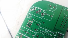
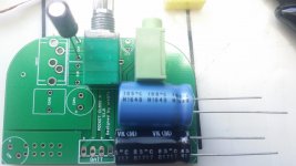
My PCA PCB arrived and I've began populating it and have some questions and concerns.
1 - My board arrived with a dent. It seems only superficial, but nonetheless it bugged me a little and needed to get this off my chest.
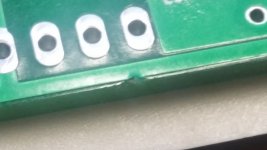
2 - I managed to get some solder in the holes for the pot, and I managed to nick some soldermask and create a bridge during the removal process. I take it this is still fine since these pins appear connected on this side anyway, but would like to confirm.
I am building the low impedance variant; the following pertains to layout/BOM:
3a - BOM notes for C2 mention attaching a a 2.2uF film cap, but the BOM lists a 1uF cap - am I misunderstanding or is this inconsistent? Which one to use?
3b - is MKT fine to use in lieu of MKS? I ordered 1uF MKS but locally I can only source 2.2uF in MKT.
4 - How to fit the 2.5mm SILMICs in C1? Imgur: The magic of the Internet Is there a pic of a board with this BOM implemented?
5 - C2_1 doesn't fit on the output side. Imgur: The magic of the Internet
6 - C3 doesn't fit.
1 - My board arrived with a dent. It seems only superficial, but nonetheless it bugged me a little and needed to get this off my chest.
An externally hosted image should be here but it was not working when we last tested it.
2 - I managed to get some solder in the holes for the pot, and I managed to nick some soldermask and create a bridge during the removal process. I take it this is still fine since these pins appear connected on this side anyway, but would like to confirm.
An externally hosted image should be here but it was not working when we last tested it.
The soldermask on the board is really fragile.I am building the low impedance variant; the following pertains to layout/BOM:
3a - BOM notes for C2 mention attaching a a 2.2uF film cap, but the BOM lists a 1uF cap - am I misunderstanding or is this inconsistent? Which one to use?
3b - is MKT fine to use in lieu of MKS? I ordered 1uF MKS but locally I can only source 2.2uF in MKT.
4 - How to fit the 2.5mm SILMICs in C1? Imgur: The magic of the Internet Is there a pic of a board with this BOM implemented?
5 - C2_1 doesn't fit on the output side. Imgur: The magic of the Internet
6 - C3 doesn't fit.
An externally hosted image should be here but it was not working when we last tested it.
I mentioned this already but maybe some have missed it - the BF862 and other SMD components are available from LCSC, a reputable Chinese retailer, for dirt cheap.
Only thing LCSC didn't have was 805 ceramic capacitors, as there is currently a worldwide shortage, but they did have 1206s which fit fine.
I don't mean to keep spamming the thread, but I don't see where I can edit a post - maybe I can't since my posts still have to be approved by mods. Anyhow, a revision and an addendum:
The MOSFET also wasn't available at LCSC, and I hadn't stumbled upon the list of alternates when I placed my order so I can't comment on those.
Importantly, they also have a $4 off first order promotion, but you can get $8 off if you go through their sister site EasyEDA.com
My board arrived with a dent. It seems only superficial, but nonetheless it bugged me a little and needed to get this off my chest.
Sorry about that - I just pull these out of the bag from PCBway and 99% of the time they have been fine as yours is the first to report a dent. If it bothers you I will send you another at no-charge via un-tracked paper mail.
I can't see your images. You should try to upload to DIYA as part of post directly, then there won't be broken links.
If it bothers you I will send you another at no-charge via un-tracked paper mail.
I'll bank that IOU for the moment
") Thanks
ThanksThey should work if you right click and open in new tab, but I figured out how to upload them now, and they're attached.I can't see your images. You should try to upload to DIYA as part of post directly, then there won't be broken links.
I also managed to figure out some of the previous list:
1 - taken care of
2 - need clarification
3a - need clarification
3b - need clarification
4 - taken care of - they can fit if one lead is straight down and the other bent 90 degrees and then back down vertical
5 - taken care of - silly me was placing the input can in the wrong footprint leaving no room for the output can
6 - need clarification - I don't think these can fit in any fashion that doesn't block the outer 2 power pins, which I don't really care about since I was never planning on using serial power, but would still like to know if I'm missing something obvious
have some more
7 - this isn't clear to me from the OP and one of your more recent posts has brought it to my attention - do I need a "cap multiplier" board or any other "adapters" if I am to power straight from a boost board? I was planning on hooking up a TP4056 board to a 3.7V lithium cell and then boosting it to 18v
8 - I seem to have neglected buying 100k resistors but I managed to salvage some from a mid-90s Philips CDROM PCB - want to double check that other qualities (thin film, 1%, etc) are not critical so long as they measure at 100k?
Attachments
Here’s how to install the caps - see link.
That...doesn't clarify anything? The caps cover the inner holes on the power pins...which that picture doesn't show...
Right angle connector might be a more elegant solution - I've fashioned one that's almost flush out of some SCSI pins from aforementioned CDROM.
Would appreciate clarifications on other points, particularly the 1uF/2.2uF discrepancy in the BOM, and using boosted voltage source. Thanks.
The caps cover the inner holes on the power pins...which that picture doesn't show...
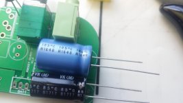
There's only 2 sets of holes for caps per channel - you can figure it out. Just bend the legs 90 deg, add shrinktube on +ve to prevent short, insert into the holes (closest to bent legs) observing polarity, and solder. That picture shows all you need to know.
3a - BOM notes for C2 mention attaching a a 2.2uF film cap, but the BOM lists a 1uF cap - am I misunderstanding or is this inconsistent? Which one to use?
3b - is MKT fine to use in lieu of MKS? I ordered 1uF MKS but locally I can only source 2.2uF in MKT.
C2's are the output caps, and to give yourself the most room, use the ones that have the round silkscreen on them (for the electrolytics) and leave the box cap unpopulated from the through hole side. Mount the 1uF or 2.2uF film cap (MKP or MKS) on the SMT side, if desired. Some people say it sounds better without the film bypass cap. So any value 1uF or 2.2uF film cap can work as bypass for C2.
This picture should make it clear how to mount caps:
Attachments
Last edited:
Yes, it sounds like the DCA has quite a few people asking for a kit. The kits are just a pain to put together but I will try. So will take some time for me to order the stuff and have all on hand. I just built a second DCA and it works well. It’s a very easy build and the amp is very satisfying to listen to. Very powerful and has no problem driving low impedance phones when running 140mA bias current.
Yes, it sounds like the DCA has quite a few people asking for a kit. The kits are just a pain to put together but I will try. So will take some time for me to order the stuff and have all on hand. I just built a second DCA and it works well. It’s a very easy build and the amp is very satisfying to listen to. Very powerful and has no problem driving low impedance phones when running 140mA bias current.
Will keep an eye on the shop!
OK, so I have assembled my unit to a working state and...it sounds really good. It's my first amp so I don't really have much to compare it to...
Some notes:
Some notes:
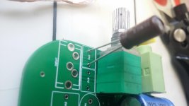
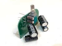
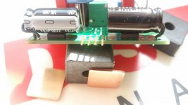
- using right angle pins stolen from an ancient SCSI drive for the power connector allows for capacitor heights up to 27mm but unsure if there any more appropriate caps on the market in that dimension. pic is without the connector housing.
- the board does get hot - the mosfets seem to get to 65-75c or so pretty quickly...is the PCB 2oz copper? i'll be using some copper "shims" attached with sekisui thermal tape as heatsinks, and then maybe again via thermal pad to enclosure
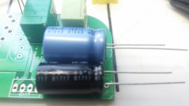
- i'm using some hard rubber standoffs stolen some from an old laptop to lift the power caps off the PCB and get the leads to their holes easier
- i'm fairly certain it does sound significantly better with the film caps, but i'll have to give it another spin without
- how can i make it 20% louder?
Attachments
You don’t need to worry about adding more heatsinks - there have not been any issues of thermal problems without additional heatsinks. Unless you are running some really ‘hot’ MOSFETs and JFET combo that is making more than 80mA bias current. Small aluminum fins attached with white RTV works well for some people too. I personally have never used any heatsinks. I do apply Kapton tape to inside of tin to increase radiative transfer by 4x to 5x.
This is untested, but try changing R4 to 33R and R5 to 220R to see if extra gain (circa 14dB total) helps. Measure the voltage at source of MOSFET and make sure it’s not too far from 1/2 of Vcc otherwise you may have volume but could clip prematurely if too far off.
Good to hear that it sounds good. It is one of the best sounding amps for the price up to about $700 to $1000 even.
I do apply Kapton tape to inside of tin to increase radiative transfer by 4x to 5x.
I have kapton tape and I understand what it does, but I'm not getting this concept. The kapton is so the the heat stays in the copper?
This is untested, but try changing R4 to 33R and R5 to 220R to see if extra gain (circa 14dB total) helps.
Following low impedence BOM, R4 is already 33R and R5 is currently 270R. I don't need 20% exactly, just a little more kick, as the source I'll be using most often is rather weak...
Kapton on inside walls of the the mint tin case increases emittance from 0.2 to 0.9 so that heat transfer via infrared transfer from PCB mint tin case is enhanced by 0.9/0.2 factor. Shiny metal is a poor infrared radiation absorber. But Kapton is excellent. Actually, even white masking tape or black electrical tape works too.
You don’t need to apply anything to PCB or MOSFETs.
You don’t need to apply anything to PCB or MOSFETs.
- Home
- Group Buys
- xrk971 Pocket Class A Headamp GB