A sneak peak at my new project, another collaboration with Hugh Dean. The HyQu - hybrid quasi-complimentary headphone amp. Gorgeous powerful sound and able to drive low impedance phones with low distortion of THD 0.008%. Remains Class A up to 500mW output into 55ohm cans. Just got it working in stereo now. When pushed hard, distortion approximates signature of SE Class A amp. I have tested it up to 30v rail supply and 115mA bias. Nominally runs at 24v Vcc and 65mA bias.
Attachments
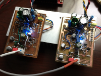
Thanks Zman and Prasi. Thank you to Hugh Dean (Aksa) for helping me with he design. This is one of the first Class AB amps that I have built that is dead quiet with headphones, and also the first discrete output Class AB with a single rail power supply. It sounds very very nice.
Thanks StellarE - I like the name too. ")
I need to put amps side by side for a comparison. First impressions without comparing AB is that his amp has effortless power, and can be brutally loud yet clean and undistorted. Sims show 20v peak to peak into 55ohms with no hint of strain. The sound is very neutral and highly resolved. This will be somewhat dependent on choice of output caps. Currently a cheap no name Chinese 2200uF 25v and Silmic II 10uF 35v bypass. The dynamics are simply jaw dropping. Almost the same as the balanced drive PCA. Maybe similar? Won't know until side by side. It runs very cool. Maybe 3 to 4 w dissipation. Could almost be battery powered as draws same current as PCA at 65mA but 24v. I could drop to 18v and 55mA and it would be identical power consumption. Initial measurements into usual 270ohm load resistor at 1.41v rms shows 0.0084%THD with H2 at -82dB and H3 at -12dB below that.
Regarding home etched boards: thanks - I followed Still4given's tips and use HCl and peroxide etch solution with laser printer iron-on transfer from PDF file onto vinyl shelving film.
Last edited:
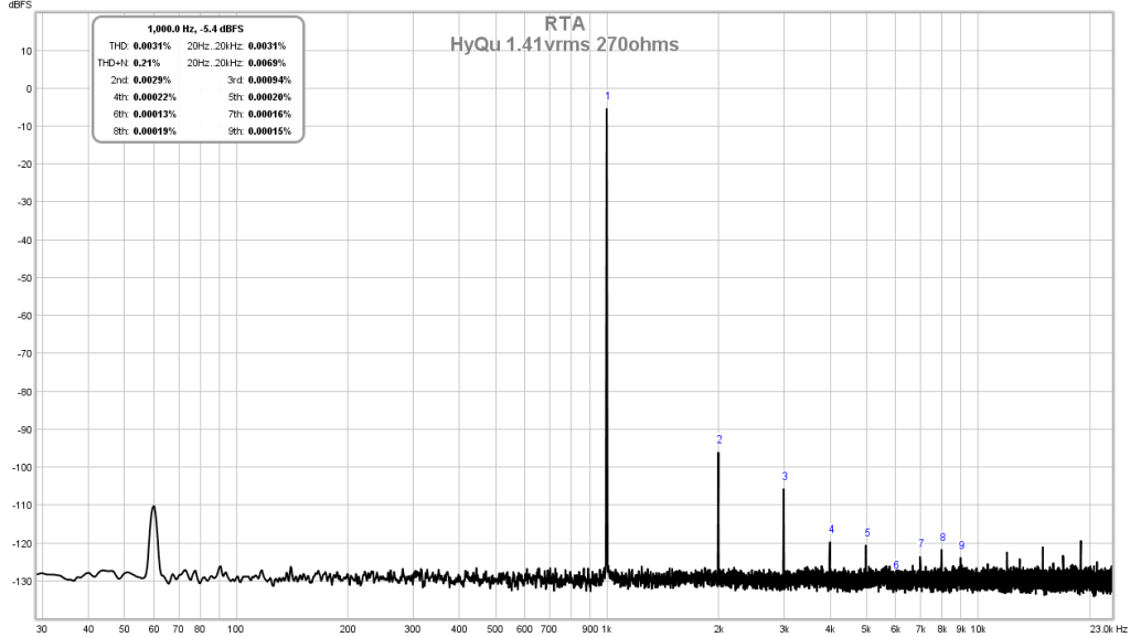
FFT of HyQu prototype
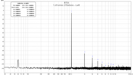
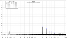
This new HyQu amp measures exceedingly well. Here is 1.41v rms into a 270ohm load. The THD is about 0.003% and H2 is about 28ppm and H3 is about 9ppm. Noise floor is flat at -130dB (Limit of the Focusrite 2i4). The harmonic distortion components decrease monotonically, This performance is quite astonishing and explains the highly resolved sound signature. Keep in mind this is a hand etched, hand drawn prototype board made with common (no boutique or even stuff like Mills resistors). Left and right channels:
Left

Right
This new HyQu amp measures exceedingly well. Here is 1.41v rms into a 270ohm load. The THD is about 0.003% and H2 is about 28ppm and H3 is about 9ppm. Noise floor is flat at -130dB (Limit of the Focusrite 2i4). The harmonic distortion components decrease monotonically, This performance is quite astonishing and explains the highly resolved sound signature. Keep in mind this is a hand etched, hand drawn prototype board made with common (no boutique or even stuff like Mills resistors). Left and right channels:
Left
Right
Attachments
PCAH
Finally got my PCAH up and running. Fried the first one due to cap rolling
This one allows me to change batteries easily and I prefer a 1/4" headphone connector. Otherwise has a combination of Similic and Nichicon caps per some of the more enlightened builders. Many thanks. Running 61ma bias with small heatsinks attached. Drops a bit as the 9 volts discharge.
Loving the sound. Thanks X for your great work.
David
Attachments
Very nice implementation. I completely forgot about the battery drawers. I used them on
a build before, but can't remember what it was. They are perfect for this application.
Well done. Does the DC in charge the batteries, or run the amp? Or both?
OK, this is getting weird. 'X' and I using the same opening phrase. (I didn't copy him, I promise.)
a build before, but can't remember what it was. They are perfect for this application.
Well done. Does the DC in charge the batteries, or run the amp? Or both?
OK, this is getting weird. 'X' and I using the same opening phrase. (I didn't copy him, I promise.)
Increasing Vcc does increase bias current but is different from changing R4 as that affects the balance of H2/H3 levels in addition to changing bias. But higher bias in general lowers overall THD. You can use 1500uF, not critical but bigger the better.
So it sounds like it is more preferable to increase bias by adjusting R4 over increasing power supply voltage Right?
Thanks guys. This one came from Mouser BX0026 Bulgin | Mouser
A little pricey, I am guessing you might find them for less. For me it was part of a larger order and I like having as much come from one source.
DC in is for powering amp only. Trying to keep it simple, plus I am not sure of 9vdc lithium batteries charge requirements. Using a HP 16vdc printer power supply, 10usd on that auction site. Just chop the connector off and put yours on.
Question regarding bias levels, how far can you take the MOSFET. I would like to build a more no holds barred!!
Yes that is the one on Mouser Funch
Yep, that is a Switchcraft plug on the side and switches from battery when plugging in the AC adapter
Last edited:
Question regarding bias levels, how far can you take the MOSFET. I would like to build a more no holds barred!!
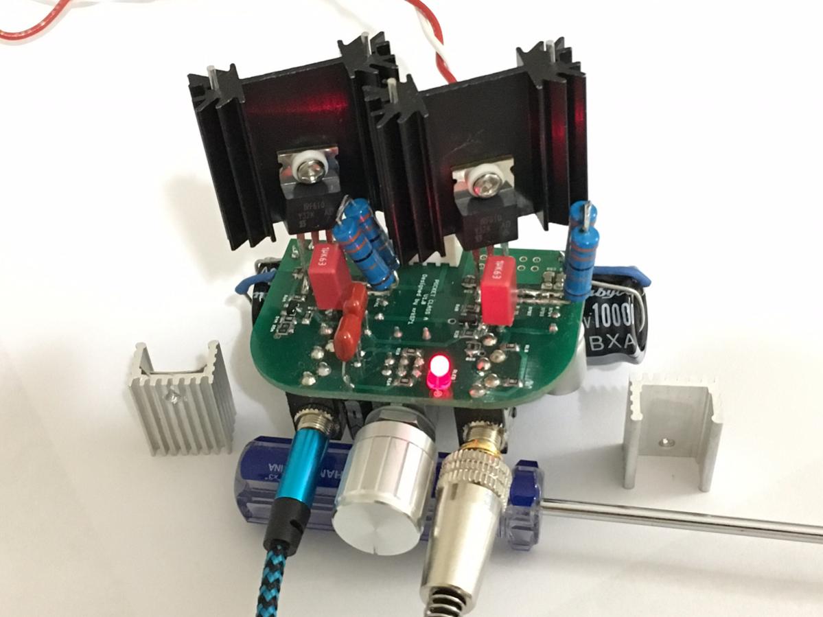
You will exceed the power rating for the resistor array if you go past 75mA. If you clamp the SMT side down on heatsink and use silicone spacer, you can increase the thermal dissipation. My guess is that 115mA is about all the bias you will need but will need to redesign resistor network to get new voltage and bias desired.
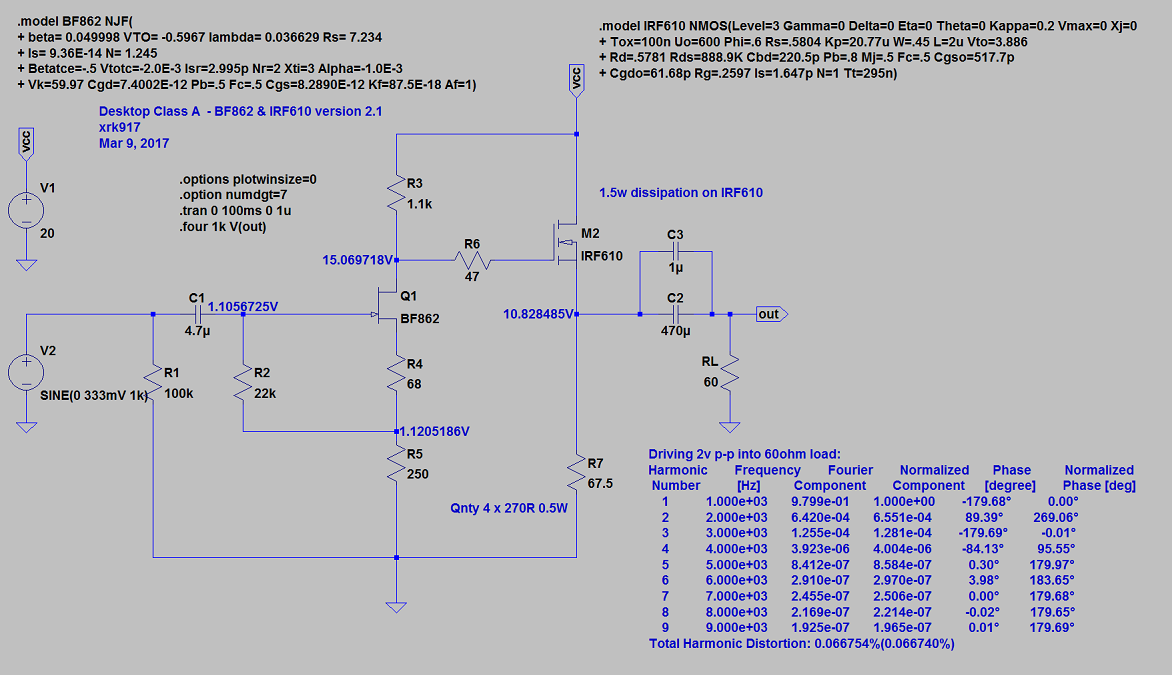
You could just follow my schematic for the desktop version and solder bent pin legs of an IRF610 to where the ZVN's go (they're GDS so pin compatible). Use two 33R 2w resistors in series and solder with bent little feet sit hey stand up. Mount external heatsink fins into IRF610. Change a few resistor values including R2, R3, R4, R5, R6, R7. Use as big of an output cap as you can afford. 2200uF is about right. Use as big of a rail caps as you can find. I am using 10,000uF 25v and it increases stereo separation. As shown with 19v rail the bias was about 115mA. Nice sound with low impedance cans.
http://www.diyaudio.com/forums/group-buys/302859-xrk971-pocket-class-headamp-gb-38.html#post5014544
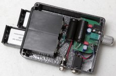
Mine ended up looking like this:
http://www.diyaudio.com/forums/group-buys/302859-xrk971-pocket-class-headamp-gb-38.html#post5014544
Mine ended up looking like this:
Last edited:
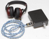
Here's a guest post review I wrote up after building this amp:
https://audioprimate.blog/2017/07/24/pocket-class-a-diy-headphone-amp-by-xrk971/
All-in-all, it's a great amplifier! Sound is excellent and it pairs really well with what I assume to be the typical companion gear (smartphone, streaming services, mid to high impedance headphones).
Well done, XRK!
https://audioprimate.blog/2017/07/24/pocket-class-a-diy-headphone-amp-by-xrk971/
All-in-all, it's a great amplifier! Sound is excellent and it pairs really well with what I assume to be the typical companion gear (smartphone, streaming services, mid to high impedance headphones).
Well done, XRK!
- Home
- Group Buys
- xrk971 Pocket Class A Headamp GB