Hello All,
I think I am now ready to manufacture.
Here are the documentations.
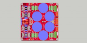
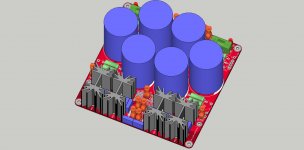
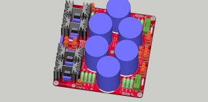
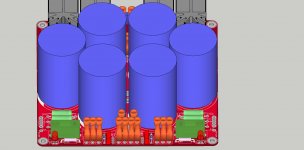
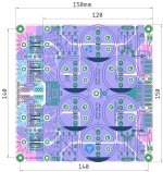
Also attached is the 3-D models and tentative BoM.
Please go through , if anyone spots any error, please let me know and i will incorporate the changes.
ALso as an option, it was suggested by P16 to open a separate thread , because it will make me easier to edit first page and upload latest document and info. I am ok with either.
regards
Prasi
I think I am now ready to manufacture.
Here are the documentations.
Also attached is the 3-D models and tentative BoM.
Please go through , if anyone spots any error, please let me know and i will incorporate the changes.
ALso as an option, it was suggested by P16 to open a separate thread , because it will make me easier to edit first page and upload latest document and info. I am ok with either.
regards
Prasi
Attachments
-
 3d1.jpg378.4 KB · Views: 1,103
 -
 3d2.jpg261.2 KB · Views: 1,018
 -
 3d3.jpg323.5 KB · Views: 966
 -
 3d4.jpg285.2 KB · Views: 962
 -
 CRCRC-PRASI.jpg805.2 KB · Views: 600
 -
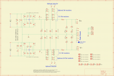 SCHEMATIC-CRCRC.png74.5 KB · Views: 767
 -
bulk PSU - r4_ListByValues.zip10.7 KB · Views: 215
-
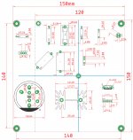 COMPONENT DIMENSIONS-CRCRC.jpg463.7 KB · Views: 728
Separate thread for CRCRC PSU PCB created")
Its done, a separate thread here has been created.
GB: CRCRC PSU
Request everyone to post relevant questions/info/subscription there.
Regards
Prasi
Its done, a separate thread here has been created.
GB: CRCRC PSU
Request everyone to post relevant questions/info/subscription there.
Regards
Prasi
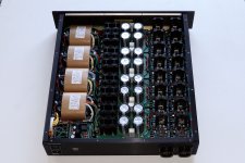
Hi Prasi,something like this?
Caps 40mm.
One can cut it at 147mm and use a separate external bridge and supply the o/p of the bridge to caps.
fuse optional.
I like this version, you could place more info about this plate, greetings
Hello.
I’m upgrading this PCB from 2-pin capacitors to 5-pin snap capacitors.
Second + and - pin’ pads are not connected on that board.
What is a reason for that?
Pin’s contact area with pad looks quite small for hight current, even soldered.
Should I connect second + and - pads to first ones?
I’m upgrading this PCB from 2-pin capacitors to 5-pin snap capacitors.
Second + and - pin’ pads are not connected on that board.
What is a reason for that?
Pin’s contact area with pad looks quite small for hight current, even soldered.
Should I connect second + and - pads to first ones?
I am planning on using this PSU for a First Watt J2 clone build. When I asked about avoiding loud pops when turning on/off the amp I was told that an inrush current limiter like a CL60 typically helped while turning on the amp and it is used in some PSU designs. I don't know if something similar is there on the CRC PSU. Can someone please confirm?
I did read the post. However the link inside is broken and I wasn't interested in that project so the rest of the discussion was lost on me. Googling gave me the link (Soft-Start Circuit For Power Amps) and I thank you for pointing me to this great article. It is a must read.
The oversight on my part was of thinking that I would draw 8Amps on the primary. Since my transformer secondary is 2x18V + 2x12V = 60V drawing a total of 8Amps, the transformer VA comes to 60*8 = 480VA or say 500VA. Since the primary is 230V, the current on the primary is approx 2.2 amps (500VA/230V). If we wanted to limit the inrush to 200% of this value (2.2x2 = 4.4Amps) a 5A rating NTC thermistor is fine.
Why the NTC is on the primary side I believe is because the inrush stresses the transformer as well. As the article states, the primary winding for 500VA transformer is about 3R so the primary current could be upwards of 70A (230V / 3R).
However, the article discourages the thermistor only approach and instead proposes a thermistor with a timed relay partly to avoid the continuous heating of the thermistor.
- Home
- Group Buys
- CRC Power Supply (Class A amplifier)