Tomorrow I will get PCB's in my hand as committed by manufacturer. After inspection, I will start preparing packages and sending out invoices and that's hell of a lot of work!. If there is any discrepancies in invoice qty and actual requirement , pl let me know.
This GB will be a bit loss to me as the unprofessional PCB manufacturer increased the invoice cost despite giving me a committed quote. I argued with him long and hard but to no avail. That's why so much delay compared to earlier timelines, sorry for that. Things are a bit different here in India.
But I have already committed a cost to you people and will not increase prices.
Just wanted to share , thank you all for your kind patience and belief in me and appreciation by those who have been a part of previous GB's. You people have made me a part of this DIYA, ....honoured!.
request all to pay up ASAP to the invoices received and will send out packages the next day.
Thanks and regards
Prasi
Hi Prasi,
Invoice recieved and paid at once. Thank you for your efforts
") and for the opportunity to get those nice boards !
and for the opportunity to get those nice boards !Best regards
rephil
Hi Prasi,
Invoice recieved and paid at once. Thank you for your efforts
Best regards
rephil
Hi rephil,
yes, you were the first person to be the quickest from sending out invoice by me and receiving payment from you!.
your pcb will be shipped tomorrow.
thank you for your support, appreciate it.
regards
Prasi
When I have to send some pcb this is a bad time for me when I see all these cards!biggest stash of PCBs I have ever seen.
Sunday is ruined as I have to work (packing and labelling)
Good luck, Prasi!
my father used to say, 'change of work is rest'!.When I have to send some pcb this is a bad time for me when I see all these cards!
Good luck, Prasi!
so its actually rest!.
still so many things on my mind for this GB and tomorrow's work plan, i cant seem to sleep, its almost 12.16am. its usually the case with me.
package will be on your way tomorrow, the designer...
Hi Prasi/Project16
Is there a way to bypass those rectifiers and use the external bridge rectifiers similar to the case of Universal PSU boards that we have on the store? I know that the boards cannot be broken down as in Universal but can the wires from the external bridge rectifiers be used after the rectifiers or is it difficult to manage as the traces on the board will interfere?
thanks
analogdiy 4 boards (confirmed),yes, 4 *, shipped
PauloPT 2 boards (confirmed), yes, 2, shipped
Voysto 4 boards (confirmed),yes, 4
ravid 4 boards +2 (confirmed), 6 pl share your details
touchdown 4 boards (confirmed),yes , 4, will ship tomorrow
xrk971 (ver1 or ver 2) 8 boards (confirmed), YES, 8, shipped
avinunca 2 boards (confirmed),yes, 2, shipped
AdeS 2 boards (confirmed),yes, 2
bk856er 4 boards (confirmed),yes, 4, shipped
Lutto 4 boards (confirmed), yes, 4
redarc12 4 boards (confirmed),yes, 4, shipped
bambadoo 4 boards (confirmed), YES, 4, shipped
Philipp23 8 boards (confirmed),yes +2, 10
hui13 4 boards (confirmed),yes, 4
patriz 4 boards (confirmed), YES, 4, will ship tomorrow
Project16 2 boards YES, 2, shipped
Prasi+friends 6 boards , 6
asanden 4 boards, yes, 4, shipped
jpr_pt 4 boards, yes, 4, shipped
spind 4 boards, yes, 4, shipped
potepuh 4 boards, yes+JLH2003(2pcb), 4, will ship tomorrow
Dennis Hui 4 boards, yes, +2+2, 8, shipped
Carmaux 4 boards YES, 4
bandol83 4 boards* YES, 4, will ship tomorrow
marcus1 4 boards, YES, 4
themystical 4 boards, yes, 4, will ship tomorrow
aubmar 2 boards, yes, 2, shipped
ZRXSHACK 2 boards, YES,+4, 6, shipped
rephil 10 boards , yes, 10, shipped
ermine22 6 boards, 6, yes, shipped
ppap64 4 boards, 4, yes, will ship tomorrow
JLOP 4 boards, 4 yes
ovidiu1 2 boards, 2, , shipped
slartibartfasst, 2 boards, shipped
thats the status as of today, will update the list again in 24 hrs.
to others who are yet to pay, if you make payment within next 10 hours, i will ship your pcb's also tomorrow.
Last edited:
Prasi to unpack the package, this tool comes with?To Potepuh,
I have packed your CRC PCB's along with JLH 2003 PCBs. Just wanted to let you know that packing is done very meticulously as CRC is 160mm and JLH is 300mm in length. So please be patient while unpacking and dont curse me.
regards
Prasi
https://fr.dreamstime.com/photo-stock-marteau-et-burin-image32928630
Prasi to unpack the package, this tool comes with?
https://fr.dreamstime.com/photo-stock-marteau-et-burin-image32928630
too good!. Unfortunately I can't make a GB for thatIf I am using 2 of these boards to power my Aleph J amp with 15000uf 63v each cap (total of 8 caps), what is the ideal resistor that I should be using with a power transformer of 0-18V @9A *2 (dual secondaries). The total capacitance will come to 60000uf per board and hence dual mono gives 120000uf more than sufficient for a Class A amp like Aleph.
it will depend upon max current draw by amp. I dont really know what it is (current) for AlephJ.
From the current , you could calculate the del V and hence power dissipated by CRC resistor.
calculate for different resistor values. ideally 0.1 ohm -0.15 ohm should be a good trade off between power dissipation by resistor / rail voltage loss and attenuation in ripple (my reading).
xrk using 0.47ohm x 3 for his build he posted here for his class A amp.
regards
Prasi
Hi Prasi/Project16
Is there a way to bypass those rectifiers and use the external bridge rectifiers similar to the case of Universal PSU boards that we have on the store? I know that the boards cannot be broken down as in Universal but can the wires from the external bridge rectifiers be used after the rectifiers or is it difficult to manage as the traces on the board will interfere?
thanks
yes , you can use.
dont populate the diodes and snubber components.
solder the V+ wire coming from the external rectifier in the diode hole thats connected to first filter capacitor of the CRC
similar thing for -ve rail. and so also for the ground wire.
you can solder the 10nf caps directly across rectifier legs.
but why do so much mods, I would get some to-220 MUR1560/2020, they are quite good.
hope this clarifies to you.
reg
Prasi
Thanks prasi, the reason is that I already have around 4 of these bridge rectifier modules and was planning to use to save some costs
By the way what is this 10nf caps? I do not see that being marked anywhere on the board or am I missing something.
Last edited:
Hello mannirajHi Prasi/Project16
Is there a way to bypass those rectifiers and use the external bridge rectifiers similar to the case of Universal PSU boards that we have on the store? I know that the boards cannot be broken down as in Universal but can the wires from the external bridge rectifiers be used after the rectifiers or is it difficult to manage as the traces on the board will interfere?
thanks
Connect the diode bridges like this. I think I did not make a mistake.
Attachments
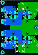
Hello manniraj
Connect the diode bridges like this. I think I did not make a mistake.
perfect!
By the way what is this 10nf caps? I do not see that being marked anywhere on the board or am I missing something.
look at my post somewhere here, there is a post with attachment containing the details in the form of a schematic. even project16's schematic (attached here in this thread) mentions those.
they are nothing but caps across diode legs.
pl download the schematic and keep it as a reference.
the sch mentions what to use and in what situation. e.g. whether one should use 10nf caps across diodes when soft recovery diodes are used.
regards
Prasi
- Home
- Group Buys
- CRC Power Supply (Class A amplifier)