Thanks Tibi for the update.
I send you a PM regarding my shipment. You gat the chance to read it?
Best Regards,
Enrico
Yes, I read it.
Regards,
Tibi
Hello Hans, to get a volume range of -63dB to 0dB, I have to use R14/R34=2K, right? The relais you are using, are they smd or thru hole? Thank you Thomas
Hi Thebo,
Yes 2K for 0dB max is correct.
The Relais are through hole, see here:
IM23TS - TE CONNECTIVITY - Signal Relay, IM Series, DPDT, 5 VDC, 2 A, Through Hole, Non Latching | Farnell element14|
Hans
Now that everything is starting to move with the Maya Controller and the VolCB etc, I had a short communication with Tibi to check if everything was still the way it should be.
We came to the conclusion that the Maya firmware for the 6 input GB board has still to be adjusted, enabling 6 instead of 4 channels.
There are 2 ways that can be taken:
- First is by delivering everybody the Maya controller with the current 4 input Firmware-1, and to supply the adjusted Firmware-2 at a later stage where everybody has to do the firmware change from 1 to 2 by himself
- Second possibility is to let me test the new Firmware-2 and to supply everybody with the Maya controller with this new firmware-2 after my O.K. has been given, avoiding users to do the firmware change themselves.
Everybody with the BPBP could, but must not use Firmware-2, except for those with the 6 input board, they MUST have Firmware-2.
To my opinion it would be better if ALL BPBP have Firmware-2, since one Firmware version makes support quite a lot easier.
What it means to flash the Firmware, look here:
http://vicol-audio.ro/maya.php
Hans
You could eventually use the same IM23TS for Re7 just as the other six relays, but then you will need to do some bending, since the IM23 has 3.2/2.2/2.2 mm pin distance and the G6K has 2.54/2.54/2.54 mm pin distances.Hi Hans,
I noticed in your BOM you specify a G6K-2P for RE7. Any reason for using a different relay here from the others?
Thanks
Reason for this G6K is that when using a 4 input or a 6 input board, this relay is replaced by a socket using partly the same holes in the PCB as the relay.
Hans
OK, so I assume when using the 4 input board Re7 is not used and replaced by a header.
I have purchased the 4 input board from Tibi as well.
That is correct.
RE7 is needed only in case of using the standard 2 input version of the BPBP.
For the 4 input and the 6 input add on's, header 2178710-8 has to be used instead.
Hans
See here for the latest version of the BOM for the VolCB and the 4 Input Board
http://www.diyaudio.com/forums/analog-line-level/291226-remote-control-bpbp-6.html#post4747325
Hans
http://www.diyaudio.com/forums/analog-line-level/291226-remote-control-bpbp-6.html#post4747325
Hans
OLED is blue and LCD is STN negative, blue transmissive.
All displays must be compatible with MAYA. A special routine is written in MAYA microcontroller to drive each display. Each display employ different controller or compatible ones.
Is difficult to make pictures as these do not render display color correctly.
Herebelow are few displays compatible with MAYA.
OLED - WEH001602A
VFD - Noritake CU16025 UW
LCD - RC1602B-BIW-ESX
LCD - RC1602B-GHW-CSX
LCD - RC1602B-GHW-ESX
LCD - RC1602B2-BIW-CSX
LCD - RC1602B2-GHW-CSX
LCD - RC1602B-BIW-CSX
Regards,
Tibi
Is the controller required anything with 6800 or SPI interfaces? That seems to be the link between the controllers used in the OLED/VFD/LCDs listed above.
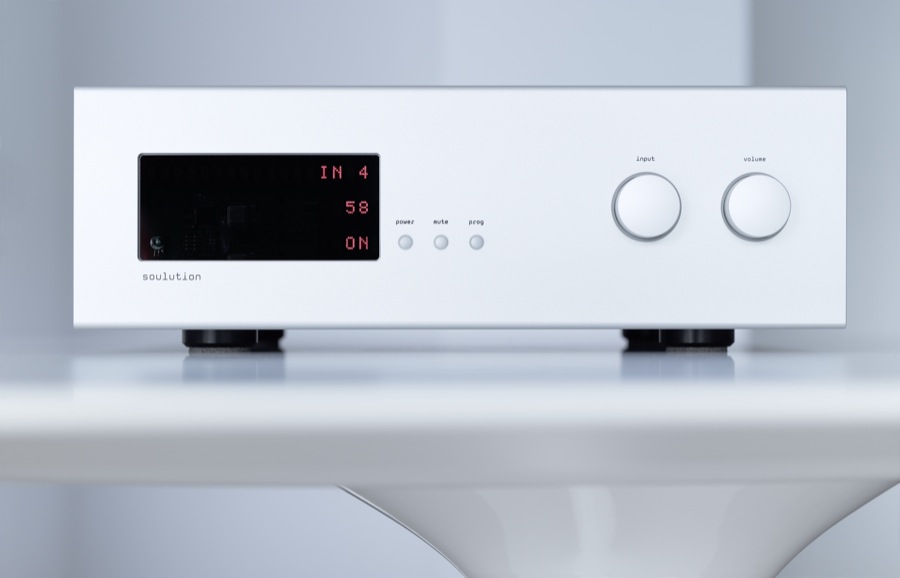
As a start, I think I'll go for a RC1602B-LLR-JWVE (red, negative) from Raystar and see what it looks like - a Soulution vibe perhaps
")
Last edited:
Now that everything is starting to move with the Maya Controller and the VolCB etc, I had a short communication with Tibi to check if everything was still the way it should be.
We came to the conclusion that the Maya firmware for the 6 input GB board has still to be adjusted, enabling 6 instead of 4 channels.
There are 2 ways that can be taken:
- First is by delivering everybody the Maya controller with the current 4 input Firmware-1, and to supply the adjusted Firmware-2 at a later stage where everybody has to do the firmware change from 1 to 2 by himself
- Second possibility is to let me test the new Firmware-2 and to supply everybody with the Maya controller with this new firmware-2 after my O.K. has been given, avoiding users to do the firmware change themselves.
Everybody with the BPBP could, but must not use Firmware-2, except for those with the 6 input board, they MUST have Firmware-2.
To my opinion it would be better if ALL BPBP have Firmware-2, since one Firmware version makes support quite a lot easier.
What it means to flash the Firmware, look here:
http://vicol-audio.ro/maya.php
Hans
Hi Hans,
Thanks for your effort with the firmware test.
I give a look to the link you post here. If I correctly understand, who will integrate the Maya with the Interface board and 6 inputs board will need the programmer from Adafruit to upgrade the Firmare-2?
About the interface board, I received yesterday the boards and I built one quickly to test the connection with VolCB. Everything is fine at the input side BUT I was so focused in the input side that I completely forget to recheck the output. So, the output connector is wrong!
My bad, I already adjusted the pcb and reordered.
Here is the link to my last post in the 6 input thread http://www.diyaudio.com/forums/grou...preampli-gb-6-input-board-17.html#post4749835
Best Regards,
Enrico
I never looked at the output signals, but their names are in reverse order indeed.Hi Hans,
Thanks for your effort with the firmware test.
I give a look to the link you post here. If I correctly understand, who will integrate the Maya with the Interface board and 6 inputs board will need the programmer from Adafruit to upgrade the Firmare-2?
About the interface board, I received yesterday the boards and I built one quickly to test the connection with VolCB. Everything is fine at the input side BUT I was so focused in the input side that I completely forget to recheck the output. So, the output connector is wrong!
My bad, I already adjusted the pcb and reordered.
Here is the link to my last post in the 6 input thread http://www.diyaudio.com/forums/grou...preampli-gb-6-input-board-17.html#post4749835
Best Regards,
Enrico
Is it really a problem when all inputs are mirrored?
And yes, you will need to buy the AdaFruits USBTiny programmer, plus all the hassle to install the drivers.
It is not a 5 minutes job to go through the learning curve if you are a novice.
Hans
Last edited:
I think a small addition to the above is needed.
The steps in the Maya display go from 0 to -63dB in 1dB steps.
The VolCB has also 1dB steps with the same 63dB range, however with the proposed resistor values it will go from +6dB to -57dB.
This means that you have to add 6dB to the value you see on the display to get the real gain.
Hans
Hans ,
the firmware can be customized for show the exact number you want.
Best regards.
Last edited:
I never looked at the output signals, but their names are in reverse order indeed.
Is it really a problem when all inputs are mirrored?
And yes, you will need to buy the AdaFruits USBTiny programmer, plus all the hassle to install the drivers.
It is not a 5 minutes job to go through the learning curve if you are a novice.
Hans
Well, was me that should recheck to board before place the order.
As you said the board is just mirrored and If just for myself I can deal with this but there are others that joined the GB and I prefer to deliver the interface that is matching the 6 input board. So, again, is my fault and I reordered the pcbs.
Regarding the programmer, you mentioned in your previous post that the Firmware-2 should work for both (4 and 6 inputs). This make sense and should be nice to have the Firmware-2 already installed instead oblige who is building the 6 input to purchase the programmer and fight with drivers, firmware, etc. This of course if don't create any problem for who is using the 4 input board
Best Regards,
Enrico
Hans ,
I can modify the firmware to print whatever you want .
Contact me/Tibi for this .
It would be great to have the correct gain in the display.
I have made the max gain 6dB as default, but some people have expressed their wish to use another setting.
The only way to get around this would be to make the max gain to be programmable with the remote control, but I'm afraid this is quite a hassle.
Coming back to the method of volume change, I communicated with Tibi the way I did this in hardware in my own remote control.
Tibi mentioned that going from X to Y as xxxxxx / 000000 / yyyyyy will be available.
Since this works flawlessly for me , I would suggest you supply the Firmware for the BPBP with the same time delay between 3.5msec and 4.5msec, after the 000000 has been first offered to the PCF chip, to give all relays enough time to break.
So as an example, 011111 will first go to 000000 and ca. 4 msec later to 100000
Will this timing be possible?
Regards,
Hans
If you find a house which can build similar chassis, can be a small GB))))
I'm thinking of making something more akin to a Nagra sized preamp, like their CDT with the display but with a data wheel and similar switches .
I'd rather see people making their own designs than all following a case GB
- Home
- Group Buys
- Maya R2R Advanced Volume controller