Preface
This run boards will be identical to rev. 1.10 boards but, obviously, without the small error that was present on fifth run.
Fifth run partecipants can have boards with a 5€/kit discount (max 1 kit), for those boards no 1€ donation to DIYAudio will be done.
Now the usual opener:
The My_Ref Fremen Edition is a variation of Mauro Penasa's My_Ref with this goals:
I've been authorized by Mauro Penasa to proceed with this My_Ref derivate amp.
You can find references on development, beta and release candidate here:
My_Ref Fremen Edition - need help on PCB evaluation - diyAudio
My_Ref Fremen Edition - Beta build/Fine tuning - diyAudio
My_Ref Fremen Edition RC - Build thread - diyAudio
My_Ref Fremen Edition - Build Thread
On my Google Drive you'll find:
Schematic
BOM
Build Tutorial
And a YouTube video on SMD soldering of FE modules.
Actual price will depend on number of partecipants/kits, the Group Buy is about PCBs only
Approximate prices (one kit = 2 PCBs, PayPal fees and 1€/kit donation to DIY audio included):
10-14 kits 38€
15-19 kits 30€
20-24 kits 26€
25-29 kits 24€
30-39 kits 22€
40-50 kits 20€
100 or more 16€
Shipping prices will be (up to 2 kits, more than 2 will be calculated):
Italy 8€
Europe 12€
Rest of the world apart Oceania 14€
Oceania 16€
PCBs (circa 12 x 10.5 cm) will be blue, 2mm tick, 2 Oz/70um copper, gold plated, made in Italy.
One transformer 160VA-300VA will be needed for each board (monoblock design)
BOM cost is around 76€ per board (premium industrial BOM) which can be lowered to 52€ (On a budget BOM).
Build a complete amp (premium industrial BOM with case, connectors, cabling. etc.) will cost around 450€ and up.
If interested please PM me your PayPal associated email address and fill your nickname, country (2 letter code) and number of kits on the Google Spreadsheet (please leave blank the 'PP account sent' column, I'll fill it so you have a feedbakc that I've received your data)
March, 7 price will be fixed and I'll start sending PayPal Invoices, all payments are due by March, 14.
Until PCB order from manifaturer is done it will be possible to partecipate to the GB
Boards will be ordered by March, 15 and should be in my hands in 15-20 days, then packaged and shipped in a week or so.
Greetings:
Mauro Penasa for his great design and kind permission
LinuxGuru for his help on new compensation
Luka for the LM318 PS initial design
KSTR for the new C9, R10 arrangement.
Soongsc, Marce, Sebaastian, KSTR and Metal for help on PCB design
BMCBob for all support, tests and reviews
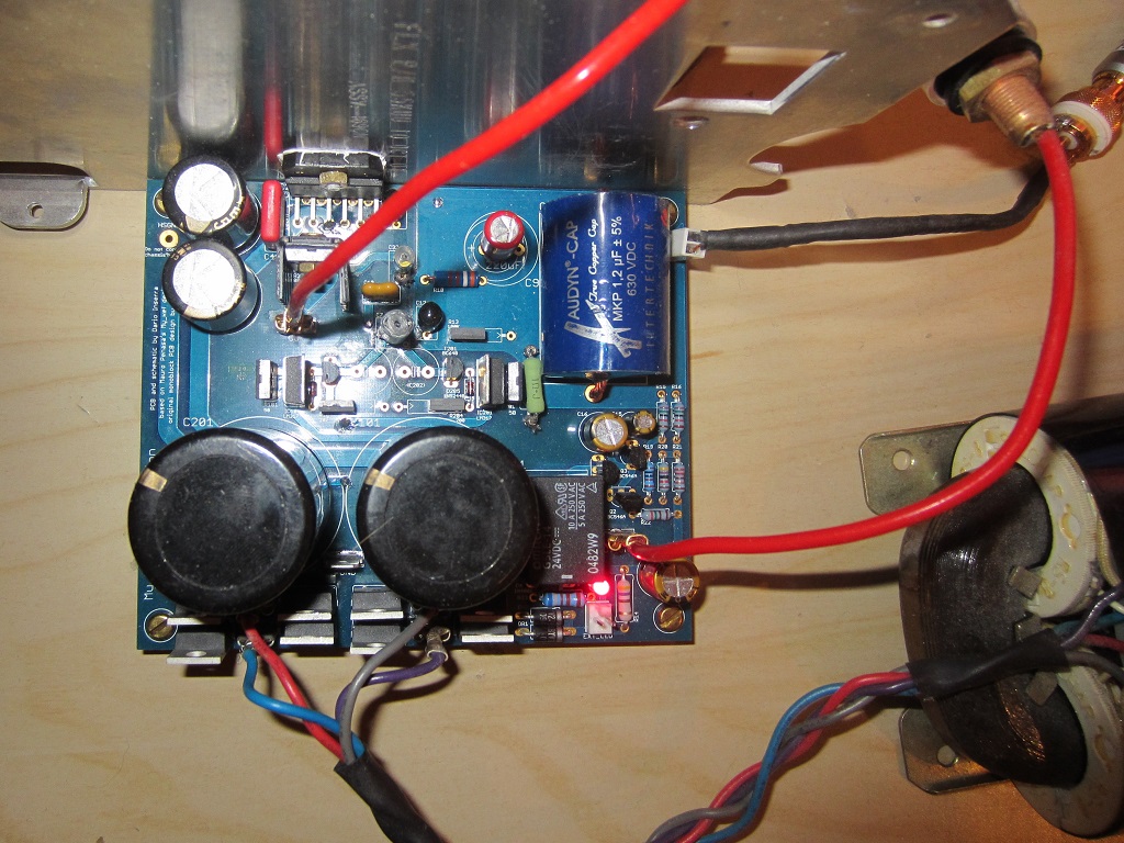
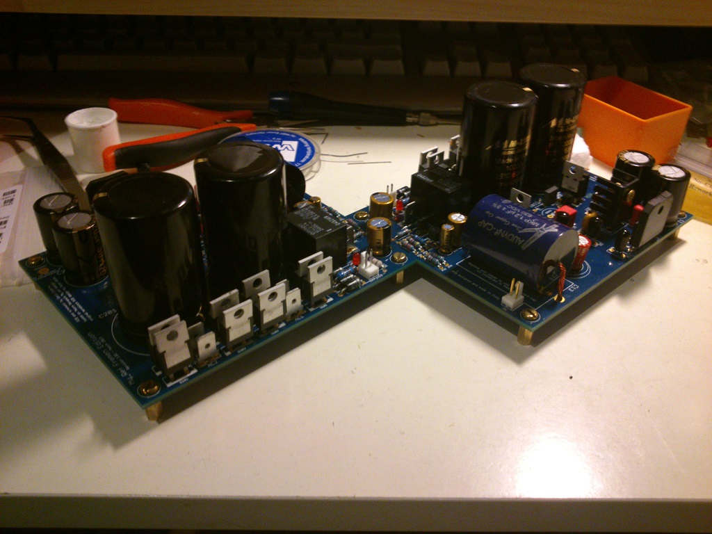
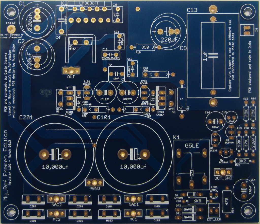
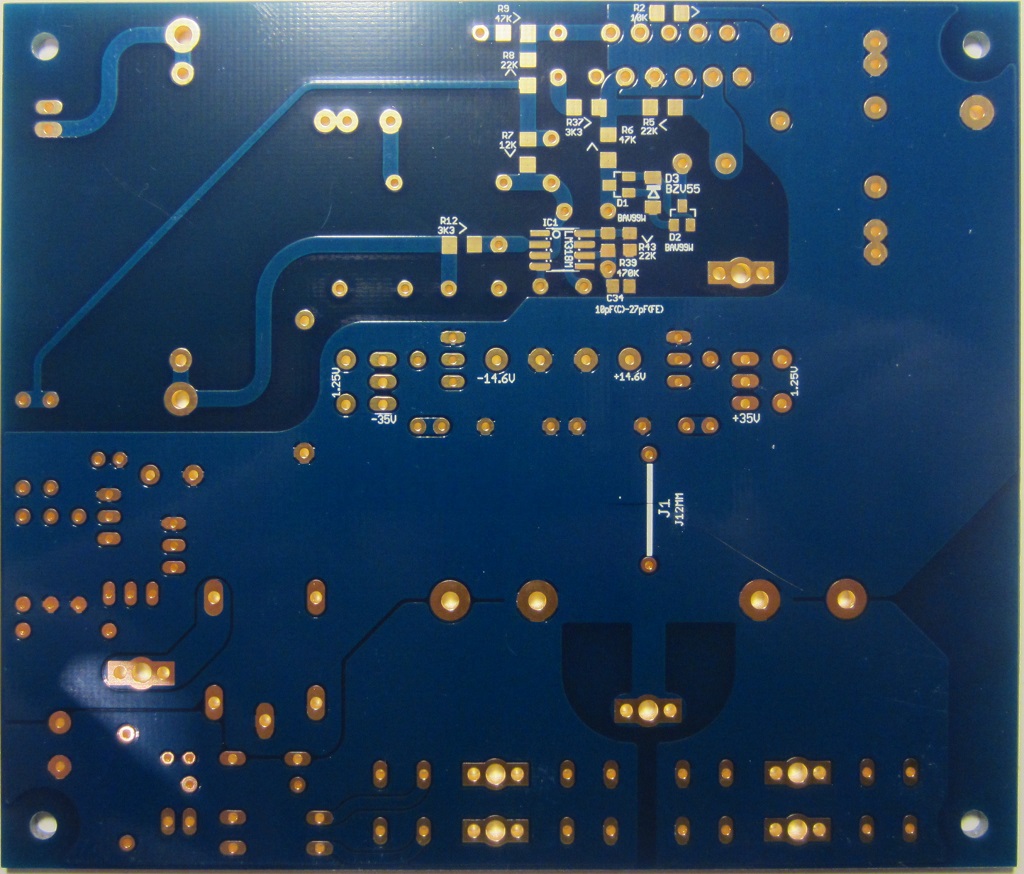
Images of boards from the first GB:
__________________
This run boards will be identical to rev. 1.10 boards but, obviously, without the small error that was present on fifth run.
Fifth run partecipants can have boards with a 5€/kit discount (max 1 kit), for those boards no 1€ donation to DIYAudio will be done.
Now the usual opener:
The My_Ref Fremen Edition is a variation of Mauro Penasa's My_Ref with this goals:
- a more stable and performing amp using SMD parts
- raise LM318's PS voltage thanks to a voltage limiter
- better PS for LM318
- bigger caps (16mm diameter with both 7 and 5 mm pads) for C1, C2, C9
- large use of SMD components
- quite all small caps and some critical resistors are still through-hole
- very small paths thanks to SMD
- ground planes design
- zener limiter based on schematic 5b from this link (which seems pretty similar to My_Evo one)
- CCS shunt PS for the LM318
- An alternate C9/R10 arrangement
- Different grounding
- Different compensation
- a double diode bridge like in most gainclones
I've been authorized by Mauro Penasa to proceed with this My_Ref derivate amp.


You can find references on development, beta and release candidate here:
My_Ref Fremen Edition - need help on PCB evaluation - diyAudio
My_Ref Fremen Edition - Beta build/Fine tuning - diyAudio
My_Ref Fremen Edition RC - Build thread - diyAudio
My_Ref Fremen Edition - Build Thread
On my Google Drive you'll find:
Schematic
BOM
Build Tutorial
And a YouTube video on SMD soldering of FE modules.
Actual price will depend on number of partecipants/kits, the Group Buy is about PCBs only
Approximate prices (one kit = 2 PCBs, PayPal fees and 1€/kit donation to DIY audio included):
10-14 kits 38€
15-19 kits 30€
20-24 kits 26€
25-29 kits 24€
30-39 kits 22€
40-50 kits 20€
100 or more 16€
Shipping prices will be (up to 2 kits, more than 2 will be calculated):
Italy 8€
Europe 12€
Rest of the world apart Oceania 14€
Oceania 16€
PCBs (circa 12 x 10.5 cm) will be blue, 2mm tick, 2 Oz/70um copper, gold plated, made in Italy.
One transformer 160VA-300VA will be needed for each board (monoblock design)
BOM cost is around 76€ per board (premium industrial BOM) which can be lowered to 52€ (On a budget BOM).
Build a complete amp (premium industrial BOM with case, connectors, cabling. etc.) will cost around 450€ and up.
If interested please PM me your PayPal associated email address and fill your nickname, country (2 letter code) and number of kits on the Google Spreadsheet (please leave blank the 'PP account sent' column, I'll fill it so you have a feedbakc that I've received your data)
March, 7 price will be fixed and I'll start sending PayPal Invoices, all payments are due by March, 14.
Until PCB order from manifaturer is done it will be possible to partecipate to the GB
Boards will be ordered by March, 15 and should be in my hands in 15-20 days, then packaged and shipped in a week or so.
Greetings:
Mauro Penasa for his great design and kind permission
LinuxGuru for his help on new compensation
Luka for the LM318 PS initial design
KSTR for the new C9, R10 arrangement.
Soongsc, Marce, Sebaastian, KSTR and Metal for help on PCB design
BMCBob for all support, tests and reviews
Images of boards from the first GB:


__________________
Last edited:
When I click the Google Spreadsheet link, it goes to the 5th run spreadsheet. Please check the link.
Fixed, thanks Jac
")
The boards from the fourth GB have IN hot and return pins labeled on the underside of the board. I find it inconvenient because when boards are assembled and mounted in the chassis it is hard to distinguish which pin is what. Measuring the resistance to ground helps to identify the input but labels on the top side would be better IMHO.
If more modifications are still possible before production I would recommend to make a provision for the second IN connector bypassing the input cap allowing the direct coupling but such that the capacitor could still be mounted and used through the standard IN connector. There should be enough space for this to the left of R15.
Just my 2 cents. Please ignore if inappropriate.
OlegSh
Hi Oleg,
While that info can easily be sourced from documentation it's not a problem to add labels on the upper side from this run on.
Modifications are possible but the one you're suggesting it's not, there's not enough space to the left of R15, you should account groundplanes and the proximity of the DC protection circuitry.
I've just tried to find a suitable position but I can't find one that satisfy me.
BTW I don't suggest anyone to DC couple the My_Ref, except for doing some tests.
The boards from the fourth GB have IN hot and return pins labeled on the underside of the board.
While that info can easily be sourced from documentation it's not a problem to add labels on the upper side from this run on.
If more modifications are still possible before production I would recommend to make a provision for the second IN connector bypassing the input cap allowing the direct coupling but such that the capacitor could still be mounted and used through the standard IN connector. There should be enough space for this to the left of R15.
Modifications are possible but the one you're suggesting it's not, there's not enough space to the left of R15, you should account groundplanes and the proximity of the DC protection circuitry.
I've just tried to find a suitable position but I can't find one that satisfy me.
BTW I don't suggest anyone to DC couple the My_Ref, except for doing some tests.
You are right Dario, it seems that there is a very limited space next to the R15. I overlooked the long trace to the DC protection on the underside of the board.
I also do not plan to use DC coupling with My_Ref FE but I like the idea of having only one capacitor in the signal path. Sometimes it can be outside of the amp...
OlegSh
I also do not plan to use DC coupling with My_Ref FE but I like the idea of having only one capacitor in the signal path. Sometimes it can be outside of the amp...
OlegSh
Since the number of kits it's on the low side I was thinking about shifting the deadline to the end of March... what do you think about it?
No hurry for me either need to source parts as well... i can wait for a better price and few more kits we are there
- Status
- This old topic is closed. If you want to reopen this topic, contact a moderator using the "Report Post" button.
- Home
- Group Buys
- My_Ref Fremen Edition GB (sixth run)