")
Hi all, I have a complete set of boards from the first run, matched(as good as you can do from a limited batch) VFETs and all antes transformers needed for the amp. Please let me know if somebody is interested. It doesn't look like I will have time to finish that project and it is such a shame it is collecting dust on my shelf.
Does anyone have a pair of boards they want to sell?
I have an extra pair of Sony VFET boards from the store - Sony VFET PCBs – diyAudio Store. PM me and we can discuss on the pricing as they belong to my friend and lying with me.
I have an extra pair of Sony VFET boards from the store - Sony VFET PCBs – diyAudio Store. PM me and we can discuss on the pricing as they belong to my friend and lying with me.
Thanks,but I want to make the VFET-1 and I already have the transformers needed.
In case someone is looking for the board but out of luck, I have a version of the Gerbers that permaneder sent me back in 2015.
Those who want the Gerbers can give me a PM with his email address.
Hi cwtim
not interested to make pcbs (already got complete kit as gift from my Bruder Generg) , but thinking that having gerbers saved as kudos to permaneder
so , you can send them , please , to >zenmodiyaudio@gmail.com<
TIA
Hi i've come across a pair of these boards and looking for a complete parts list. I notice it uses the Jensen transformer on the input and would like it switchable between XLR balanced and RCA.
I'm finding this version of the board differs to the original N. Pass one.
32VAC input from any source? Zener diode voltages? Would be great if others can share their tips on their builds of this board.
I'm finding this version of the board differs to the original N. Pass one.
32VAC input from any source? Zener diode voltages? Would be great if others can share their tips on their builds of this board.
OK!
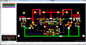
I've had some time looking at the boards and it saves a lot of confusion. Countless of hours spent on various threads studying what's on it and the circuit design. Some takeaway points:
- some of the holes have to be drilled larger - must be careful to drill from both sides half way.
- balanced connection is available but not really beneficial having only 1 half single ended buffer circuit. Jumper J1 & J2 not to be shorted if XLR connection is used. J2 appears to be just a switch to disable (when off) the buffered output of the RCA input connection to the input transformer. J1 is just a shorting switch from XLR- to GND.
- power supply for the bias circuit is already onboard so just have to supply +/- 15VDC (note dual secondaries for separate supplies on each board)
- power supply for +/- 32VDC i'm looking to save some work by buying pre-made ones online. There are many with 6 or 8 x 10,000uF caps and with screw terminals, can add the resistors that suit in original CSX1 power supply schematic, trick here is to have slow ramp on of the main voltage to allow bias power full on (this is no different to early DHT tube amps where the heater filaments must be on early or else risk cathode stripping).
Where are all the finished projects photos? A lot of boards were made but did not see many (perhaps on a different thread). I have seen some of the newer DIY Kit form of the CSX2 offered in the past by DIYaudiostore.com (but that's entirely a different board than Permaneder's ones I have). Perhaps this is more to do with the lack of supply of the 2SJ28 & 2SK82 VFETs? Perhaps the most likely case is people not having enough time or energy to finish.
Before i'm going head deep into ordering the BOM, I will need to test my 2 pairs of VFETs. All of them measured around 1.3ohms but to be 100% sure they are working correctly, have to wire them up for testing. I intend to use 2 x 9V batteries in series for the bias supply and another +/- 19VDC from a lab PSU.
Again, would really like to hear what others have done. It's reassuring that 'permanders' board (RIP), really does work.
Seems like I saw a few reports of completed boards. Permander's, and other VFet board group buys were totally eclipsed by Mr. Pass working with DIYAudio Store and making available the DIY VFet Kit, that included boards, drilled "T" profile heat sinks, and appropriate Vfets. Those builds got most of the juju.
Pass DIY Addict
Joined 2000
Paid Member
Thinking that obtaining genuine Sony VFET was a problem, i've discovered the JFETs for the input buffer is no different.
Can someone comment on the input buffer transistor that permaneder specified on the BOM. The VERY $$$ Toshiba 2SJ74BL & 2SK170BL have been out of production for quite some time and wonder why that was selected? DIYAudioStore the Linear Systems JFETs but have been reading these are not as good as genuine Toshibas. But for matched 2 pairs of LSK170/LSJ74 @ $39 seems hardly a bargain. Would buying unmatched Toshiba pairs at a lower price be the better option?
How important is matching complementary pairs? I know the input buffer has a pot to adjust offset.
Don't forget that if your preamp output impedance is sufficiently low,
you don't need a buffer.
The buffer is that suggested in Papa's article: (page 6)
http://www.firstwatt.com/pdf/art_sony_vfet_pt1.pdf
The article also suggests LSK170/LSK74 as replacements to the Toshibas.
I recall reading there are some spec differences between the LS and Toshiba parts
but the LS parts have been used very successfully.
You don't need them parts super close. Papa has recommended Idss within 1mA
as a general guideline. The trimmer might let you get away with more.
- Status
- This old topic is closed. If you want to reopen this topic, contact a moderator using the "Report Post" button.
- Home
- Group Buys
- PCBPCBs for Nelson Pass‘ CSX1 SONY VFET amplifier