Thanks!Hi Bas,
LEDs are there mainly to improve ripple rejection of the regulator, and are also, as you said, for power indication. Please note, when using RED LEDs minimum output voltage is 5V.
Hi Aleš,
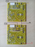
I've been wielding my soldering iron this morning and have done the basic assembly of the new regulator boards you recently supplied, some pictures below.
I'm planning to use the regulators in the power supply for a Linsley-Hood class A amp I have on the slow burner. I'll stack two regulators to create a +/-22V supply; the amp circuit, being class A, will draw a constant 1.7A from regulators. The PCBs for the amplifier were obtained from the SiliconRay store.
To complete the regulators I'll be installing LT1084 devices and offboard bridge rectifiers so some wire links still needed to replace the onboard rectifiers. I'm also considering a CR pre-filter for each regulator to make their job a little easier.
The next step will be to obtain a chassis with some substantial heatsinks as each regulator will need to dissipate around 8W (and the amplifier output devices will dissipate around 75W).
Anyway, thanks for these great little boards.
Ray
An externally hosted image should be here but it was not working when we last tested it.
An externally hosted image should be here but it was not working when we last tested it.
An externally hosted image should be here but it was not working when we last tested it.
Last edited:
Should the 120 ohm resistor be 1/2W or can I use 1/4W?
Hi,
yes, you can use 1/4W resistor or even 1/8W resistor.
Best regards,
Aleš
What if I want to use a LM337?
Hi John,
you can't use LM337. This PCB only accepts positive regulators. If you look few posts up you can see how to connect two of these PCBs to get syxmmetrical power supply.
Best Regards,
Aleš
Hi John,
you can't use LM337. This PCB only accepts positive regulators. If you look few posts up you can see how to connect two of these PCBs to get syxmmetrical power supply.
Best Regards,
Aleš
If I do it this way, do I use the same type device in both boards (i.e., LM317)?
Aleš -I need 3.3V out. Do you have a proposal for components? and do you sell components?
Hi,
use usual components, but use only one red LED instead of two, if you still won't be able to set Vout to 3.3V, try using LED with small forward voltage.
I do not provide components for this PCB.
On your e-bay site, it says the boards will take DC as input. Would this be an option to use a SMPS to run a gainclone?
Yes, it can be an option. You would improve ripple rejection from SMPS and normally you would have better voltage regulation (depends on what kind of SMPS you are using). You should disregard rectifying diodes and you shouldn't use so big filtering capacitor. 2200uF-3300uF value should be sufficient.
If I do it this way, do I use the same type device in both boards (i.e., LM317)?
Yes, you use LM317 on both boards, but as mentioned before you need to use transformer with dual voltage output and not center tapped one.
Best Regards,
Aleš
Hi Ales,
Thank you for the great boards. I have received mine a while ago and building a 12v regulator now.
I have a question, based on the description on ebay there is a C2 SMD component which is required, although I am not able to find the place for it on the board. It looks like the PCB layout on ebay page and the one I have is slightly different.
I have C20, C4
The pcb on ebay has
LOW Noise Power Supply PCB FOR LT1083 LT1084 LT1085 LM317 LM338 1pcs TPA3116 | eBay
C1: 10000uF 35V ok, looks like it is called C20 on my board
C2: 100nF 50V 1206 SMD - where should this one be placed ?
C3: 10uF 50V 1206 SMD (optional component, but will improve ripple rejection) - where should this one be placed ?
C4: 100uF 35V - is OK, still have it
Thanks for your reply") looking forward to finish the board soon !
looking forward to finish the board soon !
Thank you for the great boards. I have received mine a while ago and building a 12v regulator now.
I have a question, based on the description on ebay there is a C2 SMD component which is required, although I am not able to find the place for it on the board. It looks like the PCB layout on ebay page and the one I have is slightly different.
I have C20, C4
The pcb on ebay has
LOW Noise Power Supply PCB FOR LT1083 LT1084 LT1085 LM317 LM338 1pcs TPA3116 | eBay
C1: 10000uF 35V ok, looks like it is called C20 on my board
C2: 100nF 50V 1206 SMD - where should this one be placed ?
C3: 10uF 50V 1206 SMD (optional component, but will improve ripple rejection) - where should this one be placed ?
C4: 100uF 35V - is OK, still have it
Thanks for your reply
looking forward to finish the board soon !Hi Ales,
Thank you for the great boards. I have received mine a while ago and building a 12v regulator now.
I have a question, based on the description on ebay there is a C2 SMD component which is required, although I am not able to find the place for it on the board. It looks like the PCB layout on ebay page and the one I have is slightly different.
I have C20, C4
The pcb on ebay has
LOW Noise Power Supply PCB FOR LT1083 LT1084 LT1085 LM317 LM338 1pcs TPA3116 | eBay
C1: 10000uF 35V ok, looks like it is called C20 on my board
C2: 100nF 50V 1206 SMD - where should this one be placed ?
C3: 10uF 50V 1206 SMD (optional component, but will improve ripple rejection) - where should this one be placed ?
C4: 100uF 35V - is OK, still have it
Thanks for your reply
Hi aradan,
some of these PCBs had silkscreen error, but nothing wrong with PCB itself.
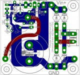
C20 = C1
C2 should be placed under C1, on your PCB under C20.
C3 capacitor is on the bottom side of the PCB, between R2 trimmer and diode D6.
Best Regards,
Aleš
LOWEST PRICE EVER!
You can now buy PCBs directly from dirtypcbs.
CLICK HERE TO BUY PCBS
What is this?
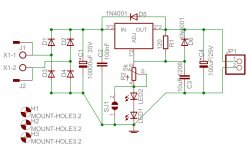
This is a universal power supply for regulators such as LM317, LM338, LM1084, LM1085, LT1086, LT1085, LT1084, LT1083 and other that have same pinout and their output voltage is configured same way.
You can now buy PCBs directly from dirtypcbs.
CLICK HERE TO BUY PCBS
What is this?
This is a universal power supply for regulators such as LM317, LM338, LM1084, LM1085, LT1086, LT1085, LT1084, LT1083 and other that have same pinout and their output voltage is configured same way.
Attachments
Just found this - thanks mravica.
I can never get the right parts when ordering - anyone do an order from Mouser or Digikey that details the correct part numbers?
Thanks
I can never get the right parts when ordering - anyone do an order from Mouser or Digikey that details the correct part numbers?
Thanks
You can now buy PCBs directly from dirtypcbs.
CLICK HERE TO BUY PCBS
What is this?
This is a universal power supply for regulators such as LM317, LM338, LM1084, LM1085, LT1086, LT1085, LT1084, LT1083 and other that have same pinout and their output voltage is configured same way.
You mention in your first post that you can use this as a preregulator, would it be possible to connect two of these board together to get even better ripple rejection?
I looked at the datasheet for LT1084 and could not find any suggestions for a dual setup for a tracking preregulating circiut as compared to datasheet for LM338 which has this pointed out, the regulators are not quite placed in series but rather in a parallel way and thus helping each-other.
Do you have any thoughts on this?
I found your PCB today and I really like the small form factor, my goal is to build a clean enough PSU for a MiniDSP 12v 1,5A and wonder if this might do the job? I have read about newer and more exotic regulator circuits using SMD mounted IC's but they all are limited to max 1A which isn't enough in this case.
- Status
- This old topic is closed. If you want to reopen this topic, contact a moderator using the "Report Post" button.
- Home
- Group Buys
- Linear regulator PCB (LM317, LT1085, LM338, LT1083)