Hi,
I would like to ask, if the old model black PCB is still available?
I need at least 3 pieces. Thanks. T.
Hello Ales,
I would like 6 of each color. Are you offering a discount on 10 like before? Please send PM for payment info. Thank You.
ZRXSHACK
Hello,
sorry, but I am out of old model. What I have now you can see in my ebay add: Linear regulator PCB. Almost the same as old model, but with better performance.
Best Regards,
Aleš
Hello Ales,
I don't want the old model. You said you had black & red boards. Are you offering a discount on 10 like before? I would like 6 of each color. Please send PM for payment info. Thank You.
ZRXSHACK
Hi ZRXSHACK,
yes I had them, but not anymore. I am waiting for new stock of PCBs, which will be similar to the ones on ebay add, will have three mounting holes and with HASL surface finish.
Best Regards,
Aleš
Hi Ales,
I would like to have 3 of the boards with three mounting holes.
How long do I have to wait?
Best Regards, Axel
Hi Axel,
I am expecting the PCBs to arrive in two weeks time.
Best Regards,
Aleš
Please let me know when they arrive ...
Will post in this thread whey they arrive.
Do you have a more recent schematic?
I must not have been paying attention because I didn't realize there were some SMD caps.
Anyway, the boards are good.
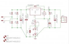
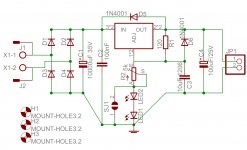
I've attached schematic. There are only two SMD caps, both of them are 1206 size and should be quite easy to solder. 10uF cap is for ripple reduction and 100nF is bypass cap for C1. If you do not want to use LEDs on the adjust pin just put solder bridge (positioned between trimmer and LED1, on the bottom side).
BR,
Aleš
Attachments
PCB are in!
Hi guys,
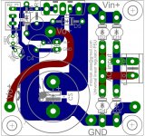
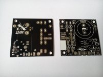
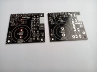
I have PCBs available again.Please see attached files for schematic, silkscreen, mounting diagram and pictures of PCBs.
Pricing:
1-10pcs -> 2€
11-20pcs ->1.85€
>20pcs -> 1.75€
priority shipping worldwide is 3€. Paypal fees also apply which you can calculate on this link: Paypal fee calculator.
Example for 5pcs = 5x2€ + 3€ + 0.82€(paypal fee) = 13.82€
When ordering please send me your paypal email and desired quantity. Upon that I will send paypal invoice.
Best Regards,
Aleš
Hi guys,
I have PCBs available again.Please see attached files for schematic, silkscreen, mounting diagram and pictures of PCBs.
Pricing:
1-10pcs -> 2€
11-20pcs ->1.85€
>20pcs -> 1.75€
priority shipping worldwide is 3€. Paypal fees also apply which you can calculate on this link: Paypal fee calculator.
Example for 5pcs = 5x2€ + 3€ + 0.82€(paypal fee) = 13.82€
When ordering please send me your paypal email and desired quantity. Upon that I will send paypal invoice.
Best Regards,
Aleš
Attachments
Last edited:
Aleš, just putting together an order for the parts and planning where I'm going to mount the modules. One observation is that your mounting diagram isn't terribly useful as it only really shows the board outline, though I guess it cold be used as a template. Although I can measure the locations it would be more convenient if the diagram showed the location location of the mounting holes (in mm) relative to the point of origin. The location of the centre pin of the regulator device would help too so that the hole for bolting them down can be easily positioned.
Ray
Ray
Aleš, just putting together an order for the parts and planning where I'm going to mount the modules. One observation is that your mounting diagram isn't terribly useful as it only really shows the board outline, though I guess it cold be used as a template. Although I can measure the locations it would be more convenient if the diagram showed the location location of the mounting holes (in mm) relative to the point of origin. The location of the centre pin of the regulator device would help too so that the hole for bolting them down can be easily positioned.
Ray
Hi Ray,
later today I will post diagram, that will show what you requested. On the other hand, this one is much easier to use. You print it without page scaling, cut it out along the board outline, place it on the surface you'd like to mount it to, mark the holes through the origins, drill the holes and that's it. It is much easier that to measure distance between holes. None the less await new mounting diagram at the end of the day.
Best Regards,
Aleš
Cheers for that Aleš. I know I could use the diagram as a template but I need to mount the regulator and the amp boards onto a substantial heatsink; when I order a chassis from modushop I'll get them to CNC machine the holes so I'll need to produce a CAD drawing, hence the request. For a little extra money modushop will produce holes that are burr free, vertical and all in just the right places!
Ray
Hi Ray,
I hope this mounting diagram helps more, than the first one posted. Mounting holes on PCB have diameter of 3.2mm. But can be drilled to bigger size.
Best Regards,
Aleš
p.s. Sorry for the delay.
Attachments
PS...what are the leds doing? Just so you can see the board is on?
Hi Bas,
LEDs are there mainly to improve ripple rejection of the regulator, and are also, as you said, for power indication. Please note, when using RED LEDs minimum output voltage is 5V.
Best Regards,
Aleš
Hi Ray,
I hope this mounting diagram helps more, than the first one posted. Mounting holes on PCB have diameter of 3.2mm. But can be drilled to bigger size.
Best Regards,
Aleš
p.s. Sorry for the delay.
That's helpful Aleš, thank you. Just need to sort out some metal to drill some holes in now!
Ray
- Status
- This old topic is closed. If you want to reopen this topic, contact a moderator using the "Report Post" button.
- Home
- Group Buys
- Linear regulator PCB (LM317, LT1085, LM338, LT1083)