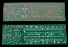
Folks, as the title says: This is a preliminary GB for a Leach Low-TIM clone based on Jens Rasmussen's last published schematic, with 2 additional output pairs for better SOAR management (and a few other minor modifications). Almost all the parts designations have been retained the same as the Jens Rasmussen BOM. With 8 + 8 2STC5200/A1943 outputs and +/- 75V rails, this should comfortably manage about 300W into 8 ohms. Higher rails are possible with appropriate transistor substitutions. Each of these boards is a monoblock of dimensions 265mm x 95mm (see attached picture).
At the moment, I have 16 boards available, but depending on the interest, I can order additional boards (for further rounds of the GB) with about 2 weeks lead time.
The bare boards are priced at USD 18 each, and I can ship up to 4 boards to most locations in the US/EU/Australasia for a flat rate of USD 8.
If interested, please add the quantity required to the thread, and PM me your email address. PM or email me (siva dot chander at gmail dot com) for questions, clarifications, details, etc.
Attachments
hi, what is the size of the boards? are they 1 oz types? thanks...
They're 265mm x 95mm with Cu thickness of 70 microns (2 oz.). I forgot to mention that there's a jumper for an optional ThermalTrak-style 3- or 4-diode chain for the Vbe multiplier. The diode chain can be mounted on a small piece of vero or perfboard and kept in close thermal contact with the heatsink, and the two ends of the chain are connected to the jumper. Alternatively, the diode chain can be omitted and the jumper shorted.
Last edited:
")
how much for two PCB including shipping?
To the Philippines (?): 2 x 18 + 8 (s&h) + 1 (paypal fees) = USD 45 total.
how many boards are up for grabs?
6 spoken for, 10 uncommitted as of now. Beyond 16, I'll probably have to batch the re-orders in lots to get a decent price break - at the moment, that minimum batch size looks to be 20, but smaller batches are possible (as few as 10 are feasible at higher prices).
It looks like the interest has been sufficient to exhaust the initial lot - all the 16 initial boards in the initial lot are spoken for. I'll accommodate any small overflows (say 2 boards) from any earlier dropouts or reduced requirements, if any.
I'll place an order for a fresh batch in about a week's time. If the residual requests on this thread on that date are 20 boards or less, that order will be for 20 boards (at the same price as the initial lot). If it is in excess of 20 boards but below 40, I may order 40 with a price break of USD 3 per board (i.e. those boards will be priced at USD 15). If the residual requests barely cross 20 but don't get close to 40, I'll take a call then whether to delay the next batch or go ahead without a price break.
To summarize, if the next batch size is:
1) 20 - no price break, and the boards continue to be USD 18 per board.
2) 40 - price break of USD 3, boards will be priced at USD 15 per board.
Tentatively, the next batch will be in my hands within about 7 + 14 days, i.e. mid-March, if there are no interruptions, changes in plans, etc.
This is a response to a query about the input DC-blocking capacitor.
This Leach clone has an input DC-blocking capacitor footprint that allows several options, with
the help of the 3-wire input connector that brings nets from both sides of the on-board footprint to the connector:
1) Use either the 5 mm or 27.5 mm pitch (or one of several alternate pitches provided with vias) and populate it with any film or electrolytic cap of your choice (radial, box-type or tubular axial) that will fit in the space provided.
2) Omit the DC blocking cap (either by jumpering it, or using the alternate input line from the 3-wire input block that bypasses the DC blocking cap).
3) Use an off-board DC blocking cap (typically one that's too large to fit on-board), using both input signals that connect to the two sides of the on-board footprint. You can also populate the on-board DC blocking cap, and use a higher-quality off-board cap to bypass it (say 5mm 1uF Wima MKS2 on-board, bypassed by an axial 0.1uF PIO or Teflon off-board).
4) Use just an electrolytic on-board - it's not as bad as people think. I've measured some electrolytics that have dissipation factors that are pretty close to some film caps, in the region of 0.3%. Of course, these could still be bypassed with a higher-quality film cap, either on- or off-board.
Any chance you might offer one of Jens' Leach clones with fewer output transistors?
In principle, you can populate this board with as few as one output pair (or any number from one to eight pairs). If the voltage rails and a few biasing resistors are adjusted appropriately, it will work. The main downside is the waste of space inside the cabinet - the PCB will extend quite a ways without anything installed on a portion of it.
You can hack off a portion of the board with a hacksaw, but you'll have to deal with repositioning the Zobel and the output inductor suitably (maybe off-board or omitted).
One could populate alternate device locations for a wider spacing of devices on a big sink.
I did the original 3pr Jens' clone and used 230W To247 using a 40Vac transformer.
It was easily able to drive any severe reactance 8ohms speaker.
Using my definition of determining the rated speaker impedance it came out as a 6ohms suitable/capable amplifier.
I could not justify the 3pr as a 4ohms capable amplifier.
It could easily drive a 4r0 load, but that is a quite different duty (although a thoroughly good test for a 8ohms capable amplifier).
- Status
- This old topic is closed. If you want to reopen this topic, contact a moderator using the "Report Post" button.
- Home
- Group Buys
- GB for Leach Low-TIM with 8 + 8 BJT outputs (bare PCB)