That is good. Keep on trying to improve the device. It seems a device many will want to build. I would like to suggest a better reg than 7805. We use MIC5205 with good results. It depends on the current draw of the LDR's etc. if you can use MIC5205. Please use separate regs for the "analog and digital world" as you call it (I like that description). 2 x 7805 is possible too but SMD regs take less board space and are less noisy. In dutch we call this remark "kicking in an open door" ")
Last edited:
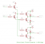
Jean-Paul: regarding my post #22, I utilise one (1) 7805 regulator to derive 5VDC and one 7806 to operate the Motor-H-Bridge
for the motorized potentiometer (6VDC - 2 transistor drops resulting in about 4.7VDC for the potentiometer - see left image).
So: there is no way to use your beloved MIC5205.
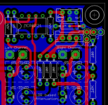
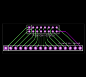
I have changed the VCPre's layout on behalf of Billyk's request (see the 2nd image).
"Standard-DIY'ers" should put a jumper on J1 (vertical), whereas Billyk should leave the jumper open and connect
5VDC/GND of another PSU to J2 (horizontal).
Coming to the prices and what I will offer you:
Depending on the number of orders, the VCPre-PCB will cost between 8-10€.
The additional PCBs (HTBypass, SPO) will cost about 5€ per piece.
The pre-programmed µP PIC16F886 will cost 4€ incl. a 28-pin socket.
I can / will offer you a MCP6021 (needed to display the attenuation) for 1€.
I can / will offer you the beautiful Fujitsu-Takamisawa relays for 1.75€ per piece.
I can / will offer you the PICOFUSE for 75cent.
I can / will offer you a BOURNS motorized potentiometer (MOUSER ID: 652-PRM162K415K104A2) for 10€. Is there any other preference?
I will talk more about the Silonex NSL-32SR2 LDRs in a further post.
Best regards - Rudi_Ratlos
for the motorized potentiometer (6VDC - 2 transistor drops resulting in about 4.7VDC for the potentiometer - see left image).
So: there is no way to use your beloved MIC5205.
I have changed the VCPre's layout on behalf of Billyk's request (see the 2nd image).
"Standard-DIY'ers" should put a jumper on J1 (vertical), whereas Billyk should leave the jumper open and connect
5VDC/GND of another PSU to J2 (horizontal).
Coming to the prices and what I will offer you:
Depending on the number of orders, the VCPre-PCB will cost between 8-10€.
The additional PCBs (HTBypass, SPO) will cost about 5€ per piece.
The pre-programmed µP PIC16F886 will cost 4€ incl. a 28-pin socket.
I can / will offer you a MCP6021 (needed to display the attenuation) for 1€.
I can / will offer you the beautiful Fujitsu-Takamisawa relays for 1.75€ per piece.
I can / will offer you the PICOFUSE for 75cent.
I can / will offer you a BOURNS motorized potentiometer (MOUSER ID: 652-PRM162K415K104A2) for 10€. Is there any other preference?
I will talk more about the Silonex NSL-32SR2 LDRs in a further post.
Best regards - Rudi_Ratlos
Attachments
Last edited:
I will get the "full monty"
I will get as a complete kit as possible, I prefer to stay with the minimum sources due to shipping costs. I live in the Canary Islands, so each time I purchase from mouser I have to pay a lot in shipping and taxes...
Thanks Rudi!!!
Jean-Paul: regarding my post #22, I utilise one (1) 7805 regulator to derive 5VDC and one 7806 to operate the Motor-H-Bridge
for the motorized potentiometer (6VDC - 2 transistor drops resulting in about 4.7VDC for the potentiometer - see left image).
So: there is no way to use your beloved MIC5205.
I have changed the VCPre's layout on behalf of Billyk's request (see the 2nd image).
"Standard-DIY'ers" should put a jumper on J1 (vertical), whereas Billyk should leave the jumper open and connect
5VDC/GND of another PSU to J2 (horizontal).
Coming to the prices and what I will offer you:
Depending on the number of orders, the VCPre-PCB will cost between 8-10€.
The additional PCBs (HTBypass, SPO) will cost about 5€ per piece.
The pre-programmed µP PIC16F886 will cost 4€ incl. a 28-pin socket.
I can / will offer you a MCP6021 (needed to display the attenuation) for 1€.
I can / will offer you the beautiful Fujitsu-Takamisawa relays for 1.75€ per piece.
I can / will offer you the PICOFUSE for 75cent.
I can / will offer you a BOURNS motorized potentiometer (MOUSER ID: 652-PRM162K415K104A2) for 10€. Is there any other preference?
I will talk more about the Silonex NSL-32SR2 LDRs in a further post.
Best regards - Rudi_Ratlos
I will get as a complete kit as possible, I prefer to stay with the minimum sources due to shipping costs. I live in the Canary Islands, so each time I purchase from mouser I have to pay a lot in shipping and taxes...
Thanks Rudi!!!
Jean-Paul: regarding my post #22, I utilise one (1) 7805 regulator to derive 5VDC and one 7806 to operate the Motor-H-Bridge
for the motorized potentiometer (6VDC - 2 transistor drops resulting in about 4.7VDC for the potentiometer - see left image).
So: there is no way to use your beloved MIC5205.
As indicated in a PM I meant it different. I would separate power supplies for digital chips and LDRs. Both need 5 V if I am correct. The LDRs will benefit from a lower noise power supply and the cost and board space are minimal. If you like the idea please decouple the MIC at both input and output with 4.7 uF tantalum SMD caps.
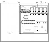
Jean-Paul: I did, separated the analog from the digital world - see the attached image on the left side.
But: since I am growing old and my eyes are getting worse and my hands are getting shaky, I am not quite sure (and have never done before),
if I will be able to solder the small SMD-regulator.
There is an alternative, using a LM317, as can been seen on the top left side of the 2nd picture.
This is AndrewT.'s comment on it:
A 7805 or 317 is perfectly good enough for the LDR supply.
You may find that making the supply slightly adjustable, say from 3Vdc to 6Vdc will make the volume adjustment "feel" more to your liking.
This would suit the 317 reg. This voltage also changes the input impedance seen by the source.
I have layouted this alternative as well and would be happy, if you (participants of the forthcoming groupbuy) are content with it
(see my fears above; I have no troubles with a TO92 device).
Billyk will of course be able to use his preferred power-supply (see the jumper on the right top side).
Best regards - Rudi_Ratlos
Attachments
Last edited:

Gentlemen, I have been asked to use a standard 16-pole ribbon DIL-to-LCD connector on the PCB and to layout a DIL-to-SIL interface
for the LCD itself.
Here we are.
Impuls: I will look at this tomorrow.
Best regards - Rudi_Ratlos
for the LCD itself.
Here we are.
Impuls: I will look at this tomorrow.
Best regards - Rudi_Ratlos
Attachments
Last edited:
Rudi, how about an issue with balance drift of LDR ? It is suppose to be known problem which can occur. As I recall simple balance pot can help.
Plus if you are using LDR to control volume maybe it is possible to use LDR instead of relays ? This would give total transparency. I am not expert by any means so sorry if question is not appropriate
Plus if you are using LDR to control volume maybe it is possible to use LDR instead of relays ? This would give total transparency. I am not expert by any means so sorry if question is not appropriate
Jean-Paul: as I told you: I have layouted a MIC5205 - version as well.
Maybe I need a magnifying glass, when I solder it.
I am willing and give it a try.
Best regards - Rudi_Ratlos
You'll like it. You will need magnifying glasses but be glad it is only a few SMD parts
Thanks for allowing changes.The standard 16-pole ribbon DIL-to-LCD connector and the DIL-to-SIL interface are good thinking.
Last edited:
I do not like digital components and digital signals near to analog signals. Because i would be move D/A to the side where is MCU and all digital ground.
Analog ground and digital ground connect with resistor to chassis over the mounting pads.
Put small multiturn trim pot parallel diode LDR for balance and capacitor to reduce digital noise.
Analog ground and digital ground connect with resistor to chassis over the mounting pads.
Put small multiturn trim pot parallel diode LDR for balance and capacitor to reduce digital noise.
Last edited:
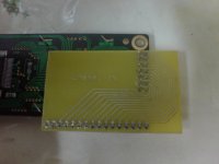
The standard 16-pole ribbon DIL-to-LCD connector and the DIL-to-SIL interface are good thinking.
This is what I am actually using, look at the attachment as an example.
It's also possible to add a couple of switches (to switch polarity) because not all LCDs have the same pin assignment when it comes to A and K backlight pins.
Attachments
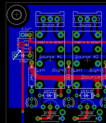
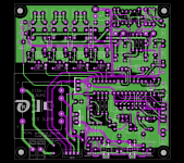
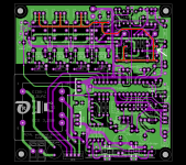
Gentlemen, I have separated the analog GND (covering the input and output connectors and the LDRs - indicated by the red line on the image
attached) from the digital GND and connected them to one another by a small (24 mil) track at the point indicated by the white arrow.
Voxxonline: concerning your question regarding the "balance drift of the LDRs":
You need 2 pairs of matched LDRs to make this project a success; the use of unmatched LDRs may result in an audible
imbalance of the two channels.
You can either buy matched LDRs here: LDRs Light Dependent Resistors Silonex NSL-32SR2 or:
"Do-It-Yourself" - which is the motto of this forum.
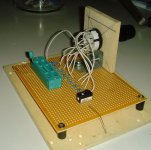
I asked each participant of the German VCPre (former version) - group-buy to pay me 20€, bought 150 LDRs (the price is about 2€ per piece),
built a small test-rig (see attached image) and measured the resistance of the photocell at various currents flowing through the LED,
the value of the current being determined by resistors on top of the LED.
I read several posts about the measuring procedure, before I started.
According to the posts the measurement should be done in a hermetically sealed room, no temperature change, no air ventilation allowed, ...
I started anyway, inserted a LDR into the ZIF-Socket, connected its photocell-resistor to my DMM and measured.
The value did not change after some seconds, I put my fingers on it, blew some air against it, ... The value did not change anymore.
It seems as if the LDRs of current batches are much more robust against exterior influences.
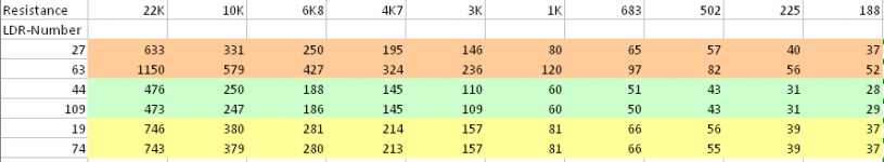
I have attached an image with some of the results of my measurements.
The LDR-pair (19,74) is a very well matched pair of LDRs (in my eyes).
The LDR-pair (44,109) is well matched again, but as you can see, the resistance of the photocell of LDR 109 is always some Ohms smaller
than the one of LDR 44. This means that the LED of LDR 109 shines brighter, but this "imbalance of the LDRs" can be compensated by the
trim-potentiometer (on the top right side of the PCB) to slightly lower the current flowing through the LED of LDR 109.
The LDR-pair (27,63) is totally un-matched and you will hear an audible channel imbalance.
I cannot tell you, how many LDRs you need to buy in order to have 2 nicely matched pairs. I guess: 10-15?
It would be best, if one of you would order LDRs for all of the participants, measure and select them as described above
and send the pairs to the participants. The process of measuring is time-consuming, though, and I will not do it again.
Voxxonline: I hope, my post answers your question concerning the "imbalance drift of LDRs".
Best regards - Rudi_Ratlos
attached) from the digital GND and connected them to one another by a small (24 mil) track at the point indicated by the white arrow.
Voxxonline: concerning your question regarding the "balance drift of the LDRs":
You need 2 pairs of matched LDRs to make this project a success; the use of unmatched LDRs may result in an audible
imbalance of the two channels.
You can either buy matched LDRs here: LDRs Light Dependent Resistors Silonex NSL-32SR2 or:
"Do-It-Yourself" - which is the motto of this forum.
I asked each participant of the German VCPre (former version) - group-buy to pay me 20€, bought 150 LDRs (the price is about 2€ per piece),
built a small test-rig (see attached image) and measured the resistance of the photocell at various currents flowing through the LED,
the value of the current being determined by resistors on top of the LED.
I read several posts about the measuring procedure, before I started.
According to the posts the measurement should be done in a hermetically sealed room, no temperature change, no air ventilation allowed, ...
I started anyway, inserted a LDR into the ZIF-Socket, connected its photocell-resistor to my DMM and measured.
The value did not change after some seconds, I put my fingers on it, blew some air against it, ... The value did not change anymore.
It seems as if the LDRs of current batches are much more robust against exterior influences.
I have attached an image with some of the results of my measurements.
The LDR-pair (19,74) is a very well matched pair of LDRs (in my eyes).
The LDR-pair (44,109) is well matched again, but as you can see, the resistance of the photocell of LDR 109 is always some Ohms smaller
than the one of LDR 44. This means that the LED of LDR 109 shines brighter, but this "imbalance of the LDRs" can be compensated by the
trim-potentiometer (on the top right side of the PCB) to slightly lower the current flowing through the LED of LDR 109.
The LDR-pair (27,63) is totally un-matched and you will hear an audible channel imbalance.
I cannot tell you, how many LDRs you need to buy in order to have 2 nicely matched pairs. I guess: 10-15?
It would be best, if one of you would order LDRs for all of the participants, measure and select them as described above
and send the pairs to the participants. The process of measuring is time-consuming, though, and I will not do it again.
Voxxonline: I hope, my post answers your question concerning the "imbalance drift of LDRs".
Best regards - Rudi_Ratlos
Attachments
- Status
- This old topic is closed. If you want to reopen this topic, contact a moderator using the "Report Post" button.
- Home
- Group Buys
- Versatile and comfortable passive pre-amp