Actually it might be reversed.
I ll check it tomorrow. Dont want to wake up daughter.
If cap is reversed it might explain delayed appearance of the problem ?
And ifit is true can I reverse it back or cap is damaged most likely?
I think you found the problem. Please use a new one. Tantalums are famous for being explosive especially after they have been connected in reverse. The mark means the + on tantalum caps. Don't know why but it adds to the already known nice firework effects that they sometimes exhibit when connected the right way. Admitted: this problem was mainly with older "drop type" tantalum caps but still...
If you have an oscilloscope you can see oscillation immediately.
Yes, you can use a 3.3µF.
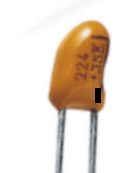
The "+ - pole" of a tanatalum capacitor is normally marked by a black dot (see attached image).
Be aware this time!
Best regards - Rudi_Ratlos
P.S. I forgot to mention that tantalum capacitors are polarized capacitors in the builder's manual.
I only mentioned this in my post #300 in this thread.
The "+ - pole" of a tanatalum capacitor is normally marked by a black dot (see attached image).
Be aware this time!
Best regards - Rudi_Ratlos
P.S. I forgot to mention that tantalum capacitors are polarized capacitors in the builder's manual.
I only mentioned this in my post #300 in this thread.
Attachments
Last edited:

Is it only in my sistem while overall sound improved 3d front to back imaging suffered a bit. Left right remains great.
Looking forward to Jean Paul ans Subbu dac improvement. I ll use it with JG buffer so it could help.
But overall sound is great.
I ll probably try different input caps in my amp or possibly dc coupling.
After all I have reference non colourating pre so it is good to play upon that
Looking forward to Jean Paul ans Subbu dac improvement. I ll use it with JG buffer so it could help.
But overall sound is great.
I ll probably try different input caps in my amp or possibly dc coupling.
After all I have reference non colourating pre so it is good to play upon that
Hello,
I finally managed to get the VCPre going and programm the remote control.
So far, everything looks allright and works as expected. I did not yet listen to it, but checked the attenuation on the o-scope, and the channels match quite well.
Thanks a lot to all people involved in the project!!! Especially you, Rudi, for the tremendous amount of effort you donate to the DIY community. As I told you via email, I already built your TO3 Symasym, and its an extraordinary amplifier!
Anyways, I have one small problem with the VCPre, the Alps motor pot isn't moving as expected. I checked, and during operation (i.e. turning the volume up and down via remote conrol), I only get around +- 3V, not the expected 6V. The voltage regulator is delivering the 6V, and the 2n551s are seeing 6V as well. Any idea on how to track down the issue (except desoldering and replacing the 2n551s?)
The second thing I noticed is that (as stated already) the attenuation display is rather coarse. In my case it only displays 0dB to -16dB for the full range. I was wondering if it would help to have something like an auto-range feature for the attenuation. During setup one could measure the Vdrop accross the sense resistor for full clockwise and full counter-clockwise turn of the pot, save the values as reference and then divide the range by, say, 40 equal steps, to display attenuation from 0 to -40dB. It would not be scientifically correct, but give a better feel for the attenuation? On the other hand, I just thought to myself, that I tested without a load, maybe this might make the difference....?
Anyways, thanks a lot for this great project again!
Best regards,
hallodeletue
Hello,
Anyways, I have one small problem with the VCPre, the Alps motor pot isn't moving as expected. I checked, and during operation (i.e. turning the volume up and down via remote conrol), I only get around +- 3V, not the expected 6V. The voltage regulator is delivering the 6V, and the 2n551s are seeing 6V as well. Any idea on how to track down the issue (except desoldering and replacing the 2n551s?)
I noticed this already and asked Rudi about it, he said it is sufficient to drive the motor.
The second thing I noticed is that (as stated already) the attenuation display is rather coarse. In my case it only displays 0dB to -16dB for the full range. I was wondering if it would help to have something like an auto-range feature for the attenuation. During setup one could measure the Vdrop accross the sense resistor for full clockwise and full counter-clockwise turn of the pot, save the values as reference and then divide the range by, say, 40 equal steps, to display attenuation from 0 to -40dB. It would not be scientifically correct, but give a better feel for the attenuation? On the other hand, I just thought to myself, that I tested without a load, maybe this might make the difference....?
A small and quick modification to get 0-100% is to use a motorized-POT that has more than 2-channel variable resistors. Connect the 3rd variable resistor upper and lower terminals to PIC's supply and connect the wiper to PIC's ADC, Rudi knows how to change the code to make it work that way and display the volume following your suggestion. It doesn't need major changes in the code, may be Rudi will not follow such a change because he spent a long time trying to implement the dB thing.
My main issue was I wanted to use a digital pot rather than the motorized-pot, it gives much more flexibility over the motor and user is able to display volume either dB or 0-100% representation.
Another thing, the code and PCB can be changed to use timer1 with a 32KHz crystal wake up on interrupt to force the PIC wake up from sleep to read the temperature sensors and display them on the 2x16 LCDs, using the WDT turned out to be problematic in some events, it caused the PIC to suddenly reset instead of waking up, also sensors reading intervals was not predictable, sometimes it was accurate and sometimes it was random.. I remember Rudi has encountered this problem and asked me to avoid using the WDT, may be solved it by assigning a remote-control key for the user to see the temperature on 1x16 LCDs and just ignored this issue for 2x16 LCDs, may be someone else helped him solving it, I don't know as I am no longer involved in this project. Actually, I encountered this issue myself and had to move to 1x16 LCD.
Last edited:
@Hallodeletue: you won't be able to measure +/- 6VDC on the motor-H-bridge connector, but you should measure a voltage of about +/- 4.5 VDC (6V - 2 x diode drops).
4.5VDC is the recommended value to operate both ALPS and BOURNS motorized potentiometers.
Keep in mind: the only thing that can be measured and translated from analogue to digital during operation is voltage.
WINEDS and I did of lot of research and tests to improve the display of the attenuation.
We agreed on keeping a lookup-table as the base.
The lookup-tables contains digitally translated (by means of the PIC's integrated A/D converter) values and the corresponding attenuation that we calculated by hand.
As the reference voltage I used the anode-voltage of a LED (about 1.80V), whereas WINEDS used a 5VDC power-supply voltage.
The result is that his lookup-table is not as coarse as mine (allthough I do not understand why), and the attenuation display is slightly improved.
But what shall I do now?
Best regards - Rudi_Ratlos
Simple, possible ADC input values is from 0-5V when using a voltage reference of 5V for the ADC itself.
You are limiting the ADC max input to 1.8V for example, while using a 5V reference for the ADC itself, so the number of possible values is less than that for Wineds who allows the ADC input to reach 5V.
If you managed to use a smaller voltage reference for the ADC itself, for example 2.5V, you will be able to fine-tune your values and get much better resolution.
Hello,
so maybe I will have to replace the 2n551s.... +/-3V is still not 4,5V ;-)
Regarding the attenuation display thing, I thought that the variation (for example -40dB with your VCPre, Rudi, or -16dB on mine) comes from the variations inherent to the LDRs, so I thought that some kind of calibration to the individual LDRs on one VCPre would improve things, and I hoped that a software update would do the magic. But of course you thought about that.
I didn't think about any hardware hacks...
Thanks, and best regards,
hallodeletue
METAL, your "proposal" in post #555 is wrong, and I am very unhappy with your answer!
The schematic senses the DC - voltage drop across a LDR safety resistor (this is the input to the MCP6021 OPAMP, which operates as a differential amplifier) and multiplies
this voltage drop by the gain of the MCP6021.
The gain of the OPAMP is set up in a way that it gives the full swing from 0V - 5V on its output, which is the input to the PIC's A/D converter.
I have manually measured the resulting voltage (attenuation) on the RCA output pin (OutV) for about 30 positions of the 100K dual - potentiometer, have determined the attenuation-value
(dbAtt = 20*log10(OutV / 1.8) and have written down the associated PIC's - ADC value into the lookup-table.
Please do not confuse the audience!
Best regards - Rudi_Ratlos
Hello,
maybe that's the explanation for me getting different results than you do. I replaced the safety/sensing resistor with a higher value than 100 ohm, as suggested in the builders manual. Actually, I used 150 ohm, if I recall correctly.
Would that account for getting attenuation display of 0 to -16dB only?
Best regards,
hallodeletue
Last edited:
- Status
- This old topic is closed. If you want to reopen this topic, contact a moderator using the "Report Post" button.
- Home
- Group Buys
- Versatile and comfortable passive pre-amp