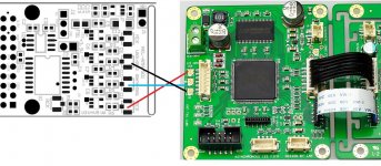
See attached. I've circled the dots on the pcb drawing that show a through hole connection that you are able to use to take the isolated i2s from before the flipflops. If feeding the i2s to Ian's FIFO this would be the preferred way of connecting IMO. Try your best to have a separate ground connection that corresponds to each i2s signal wire to achieve GSGSGSGS signal arrangement. May mean soldering the ground wire on to the SMD pad for the flip flop.
To take from the u.fl headers you would need to use a 0ohm resistor to jumper from input to output of each of the flip flop ic positions. There is often very little point in using u.fl on the input to Ian's FIFO, on the output I would go out of my way to use u.fl between FIFO and DAC but on the input, not much point IMO with the clock speeds present on the Amanero.
There is probably a 3rd option to reclock based on the amanero clock somehow but that seems unnecessarily complex when using Ian's FIFO.
Cheers,
Chris
ETA
Hi All,
I am trying to get in touch with the supplier to confirm delivery date for the boards. It has been quite a while and many have also asked me about this. Will keep pressing and as soon as I get some news I will update.
Panelizing of board is now complete and confirmed for fabrication process. Final boards as in pic. There are now 2 boards S01 and S02 (Pot chip version). However fab guys have now advised shipment from factory in China will be delayed until 22nd Feb due the Lunar New Year holidays. So 2-3 days after that I can start shipping to you all. Hope you could hang in there for a while and sorry for any inconvenience. Let me know if anyone has concerns. In the meantime I will continue with the support.
Hi All,
I am trying to get in touch with the supplier to confirm delivery date for the boards. It has been quite a while and many have also asked me about this. Will keep pressing and as soon as I get some news I will update.
See attached. I've circled the dots on the pcb drawing that show a through hole connection that you are able to use to take the isolated i2s from before the flipflops. If feeding the i2s to Ian's FIFO this would be the preferred way of connecting IMO. Try your best to have a separate ground connection that corresponds to each i2s signal wire to achieve GSGSGSGS signal arrangement. May mean soldering the ground wire on to the SMD pad for the flip flop.
To take from the u.fl headers you would need to use a 0ohm resistor to jumper from input to output of each of the flip flop ic positions. There is often very little point in using u.fl on the input to Ian's FIFO, on the output I would go out of my way to use u.fl between FIFO and DAC but on the input, not much point IMO with the clock speeds present on the Amanero.
There is probably a 3rd option to reclock based on the amanero clock somehow but that seems unnecessarily complex when using Ian's FIFO.
Cheers,
Chris
Thank you for your help.
At the second choice, why use 0 Ohm resistor?, can I bypass between the input and output IC flip-flops? . I'm confused whether there is a difference when using the 0 Ohm resistor & bypass ?.
Regards ,
Van Duy
ETA
Boards are all in fab now and expected to be completed by end of next week. Will advise shipping date soon afterwards.
Hi All,
I am trying to get in touch with the supplier to confirm delivery date for the boards. It has been quite a while and many have also asked me about this. Will keep pressing and as soon as I get some news I will update.
Boards are all in fab now and expected to be completed by end of next week. Will advise shipping date soon afterwards.
Thank you for your help.
At the second choice, why use 0 Ohm resistor?, can I bypass between the input and output IC flip-flops? . I'm confused whether there is a difference when using the 0 Ohm resistor & bypass ?.
Regards ,
Van Duy
neater and more consistent impedance, but a solder bridge or piece of flat wire does fine in a pinch
Connecting before Ian's FIFO
Ordinarily, I will be worried about using a wire link but since the signals go into to Ian's FIFO and gets regenerated anyway, it does not matter much. You could also cut one end of the UFL cable assembly, strip to get the leads and dovetail to the pin pads/header just after the isolator section of the S01 board.
neater and more consistent impedance, but a solder bridge or piece of flat wire does fine in a pinch
Ordinarily, I will be worried about using a wire link but since the signals go into to Ian's FIFO and gets regenerated anyway, it does not matter much. You could also cut one end of the UFL cable assembly, strip to get the leads and dovetail to the pin pads/header just after the isolator section of the S01 board.
Last edited:
Connecting after Ian's FIFO
Yes, there is no point clocking the Amanero Re-Clocker if connecting to Ian's Fifo unit as the input buffer will wipe out any clock signature. So isolation only if used this way.
But, there could be some benefits if this Re-clocker board is used after Ian's Fifo Re-clocker if the Ref clock used with the Amanero Re-clocker and the Flip-flop action is better than that on Ian's board- again all these are theoretical analysis
---
There is probably a 3rd option to reclock based on the amanero clock somehow but that seems unnecessarily complex when using Ian's FIFO.
---
Yes, there is no point clocking the Amanero Re-Clocker if connecting to Ian's Fifo unit as the input buffer will wipe out any clock signature. So isolation only if used this way.
But, there could be some benefits if this Re-clocker board is used after Ian's Fifo Re-clocker if the Ref clock used with the Amanero Re-clocker and the Flip-flop action is better than that on Ian's board- again all these are theoretical analysis
Last edited:
So, how much of the board is assembled? Do I need additional parts for the isolator/reclocker?
Acko's original post indicates that it's a bare board(s) and has/will provide a BOM (casually following the thread and can't remember if he already posted it)
Acko posted a parts list a few pages back, like post 350.
https://docs.google.com/spreadsheet/ccc?key=0AjMtoJzE9WFgdGZwdHBzeHFDcU9aRGZmVUhpczZGdkE&usp=sharing
https://docs.google.com/spreadsheet/ccc?key=0AjMtoJzE9WFgdGZwdHBzeHFDcU9aRGZmVUhpczZGdkE&usp=sharing
ETA
Boards are all ready and factory advised shipping today. Hope to get them by mid-next week")
Boards are all in fab now and expected to be completed by end of next week. Will advise shipping date soon afterwards.
Boards are all ready and factory advised shipping today. Hope to get them by mid-next week
You only need the parts to populate either S01 or S02. If you don't use the mute/dsdoe signals you do not need the isolator and caps for those signals. There are alternatives for the isolators that may be cheaper also, these alternatives are listed in the BOM too ...
Short answer, no you don't need all those parts.
Chris
Short answer, no you don't need all those parts.
Chris
ETA
Received boards today. Doing some inspection and will start shipping shortly.
Boards are all ready and factory advised shipping today. Hope to get them by mid-next week
Received boards today. Doing some inspection and will start shipping shortly.
Received boards today. Doing some inspection and will start shipping shortly.
Better you than me
Thanks
If I don't use u.fl, and instead mount the board very close to the DAC input, say <1cm away, what would be the best connector ? Solid core, say 18awg ? or flat copper strip, and if so, how wide ?
thanks
Well I did some reading and I figure I want 32awg (0.2mm) or smaller.I have some upocc cryo-treated cable that I can get individual strands from. Have fun trying right ;-)
- Status
- This old topic is closed. If you want to reopen this topic, contact a moderator using the "Report Post" button.
- Home
- Group Buys
- Amanero Isolator/Reclocker GB