Hi Everyone, perhaps a stupid question, but here goes.
I am making the power supply for an earlier version of the TO3 Symasym using Carlos Mergulhao PCB. The build manual suggests to wind the inductor for the Pi filter using 40 turns of enamel copper wire around a 33Ohm resistor. Is the resistor necessary or could I wind the turns around a former and then remove the former to create an air cored inductor?
Thanks
Alan
Alan, do it as Greg Erskine is telling you:
40 turns of 1.0 mm enamelled copper wire wound in 4 layers around R7 and R8 (approx. 13mH) (well: need not be 40 turns, can be 30 as well - LoL).
But: always use a resistor (Greg proposes to use a 33 Ohm resistor) to wind the enamelled wire around it.
Best regards - Rudi
40 turns of 1.0 mm enamelled copper wire wound in 4 layers around R7 and R8 (approx. 13mH) (well: need not be 40 turns, can be 30 as well - LoL).
But: always use a resistor (Greg proposes to use a 33 Ohm resistor) to wind the enamelled wire around it.
Best regards - Rudi
Attachments
40T in 4 layers will not get any where near 13mH.
Like I said, 40T is too few for a PSU filter.
A large diameter bobbin like 19 to 25mm with 100T to 200T (14layers of 14turn) is probably more like what is needed to get a reasonable inductance affect to roll off the higher harmonics.
Like I said, 40T is too few for a PSU filter.
A large diameter bobbin like 19 to 25mm with 100T to 200T (14layers of 14turn) is probably more like what is needed to get a reasonable inductance affect to roll off the higher harmonics.
Last edited:
Thank you for your replies. The question now is, if the inductor is too small a value to have any useful purpose in the power supply ( as Andrew T points out ) why is it there? Can it just be substituted with a low value resistor, say 0.1 Ohm?
If I had more space available I would wind larger inductors as suggested but this is not possible.
Thank you for your help.
Alan.
If I had more space available I would wind larger inductors as suggested but this is not possible.
Thank you for your help.
Alan.
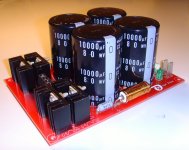
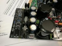
Gentlemen, I want to offer you the SYMASYM shown on the picture below.
It consists of:
- 2 PCBs "Black Beauty SYMASYM", with Backend PSU, Frontend CapMultiplier and Speaker Protection on board
- 2 pairs of matched NJW0281G and 2 pairs of matched NJW0302G
- 4 capacitors Nichicon 10.000µF/80V
The price: 65€ with shipping worldwide inclusive.
Best regards - Rudi_Ratlos
It consists of:
- 2 PCBs "Black Beauty SYMASYM", with Backend PSU, Frontend CapMultiplier and Speaker Protection on board
- 2 pairs of matched NJW0281G and 2 pairs of matched NJW0302G
- 4 capacitors Nichicon 10.000µF/80V
The price: 65€ with shipping worldwide inclusive.
Best regards - Rudi_Ratlos
Attachments
Hello everyone, I have just completed one channel of the TO3 version and am conducting some listening tests. The bias set up easily and the offset appears to be 1mV either side of 0 volts. The amplifier appears to be completely silent with no input and ear next to speaker cone.
Quality seems very nice, but have not as yet carried out comparisons with my regular amplifier.
One query that I have is that the gain appears to be slightly too high when using my normal pre amp ( Quad 44 ). I have included the 22ohm resistors on the input pair as advised. Could I alter the ratio of the 2k and 22k resistors on the input network to reduce the gain, or is this not a good idea?
Regards
Alan
Have you tried a 1kHz square wave at a few mVac input with 22nF to 100nF across the output. Output 200mVpp to 2Vpp.
Both my To247 builds oscillated, or rang badly.
I gave up trying to suppress this and both builds sit on the shelf.
Reducing the gain increases the feedback. This would reduce the stability margins and may make the ringing worse.
Both my To247 builds oscillated, or rang badly.
I gave up trying to suppress this and both builds sit on the shelf.
Reducing the gain increases the feedback. This would reduce the stability margins and may make the ringing worse.
Last edited:
Andrew T thanks for the reply. Unfortunately I do not have a signal generator or oscilloscope. However I have connected 100n and 220n capacitors to the output (with no speaker connected ) and have let the amplifier run for several hours with the input both shorted to ground and open circuit. The heatsinks stays just a few degrees above ambient and does not appear to alter. I have checked the output with a Fluke meter set to AC Hz and it shows zero. Meter spec says it will read to 50 KHz. Am I doing right ?
Finally I see that waveform generators can be had in kit form from Ebay very cheaply, about £10, any thoughts on these ?
Regards
Alan
Finally I see that waveform generators can be had in kit form from Ebay very cheaply, about £10, any thoughts on these ?
Regards
Alan
New member, lots of questions
Hi everyone,
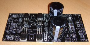
a quick intro first: My name is Oliver, I'm a software engineer from Berlin - and I'm in the process of building my Symasym based on the pcbs from diy-audio-shop. Partly out of interest, partly because I need a new power amp. The amp will be used to power Tuby6 diy speakers first but has to be able to drive ADW duettas in the future (projects on my todo..).
While the supplied manual has been very helpful, it seems to lack a BoM for the actual amplifier. The added reichelt-cart was partly unavailable and thus I have been stumbling over several things.
While I have no deeper eletronics experience (I do software only at work) I can furtunately use our electronics lab at work and have access to a good solder iron, LCR meter and wizardry like osciloscopes and function generators (though I have no idea how to use them") )
)
This thread has been super helpful, I have actually read it from front to back if you believe it
Nonetheless I have reached a certain point in my build we some advice would be very very appreciated!
The build consists of diy-audio-shop PCB, talema 25V transformers, matched 2SK170*(from a ebay source linked in this thread I believe) and NJW0281G/0302G transistors.
Currently I have both power sections complete and tested ok and have continued with resistors and diodes.
My open issues/questions:
1. I have seen some pictures, where the input transistors have been tied together using heat shrink tube - is this advisable?
2. I struggled to decide which capacitors need to be mica - I have ordered them for C2, 9, 10, 11 and 13. Is this ok?
3. For the bigger footprint capacitors in the middle of the pcb (100nF, C15,34,36) I used Wima mks4 - but they don't really fit the pcb. Also in some pictures they look bigger then the ones I used, are there different versions?
4. For the power-section I used 2*10.000µF and 4*1000µF, but sometimes 15000 and 2200 seem to be used. Is the capacity ok for me or should I "upgrade"?
5. The heatsinks I bought are a little bit too small to mount the whole board.... is it ok to drill new holes behind the rectifier heatsinks as indicated in the picture? There seems to be nothing on the pcb there.
6. I am unsure about the "active pre-amplifier" definition. I will use an old Marantz amp with a fried power amp section as pre-amp. By my understanding this is an active preamp - right? So I should use 1k for R36 and 22ohm for R29 and 30?
7. The whole CAP thing is a bit confusing - I guess for me just enable CAP multiplier and be ok, right?
8. I wound 20 rounds of 1mm isolated copper around a 10ohm 2W resistor for R28 as instructed. It has almost 1µH now (which makes me happy), but obviously way lower resistance now - this is as intended, right?
Sorry about the wall of text, any help and comments would be highly appreciated. I'm not sure if it is of any use, but I could publish my BoM once the amps are done and working and might save someone else quite some time in the future.
Thanks, Oliver
Hi everyone,
a quick intro first: My name is Oliver, I'm a software engineer from Berlin - and I'm in the process of building my Symasym based on the pcbs from diy-audio-shop. Partly out of interest, partly because I need a new power amp. The amp will be used to power Tuby6 diy speakers first but has to be able to drive ADW duettas in the future (projects on my todo..).
While the supplied manual has been very helpful, it seems to lack a BoM for the actual amplifier. The added reichelt-cart was partly unavailable and thus I have been stumbling over several things.
While I have no deeper eletronics experience (I do software only at work) I can furtunately use our electronics lab at work and have access to a good solder iron, LCR meter and wizardry like osciloscopes and function generators (though I have no idea how to use them
)This thread has been super helpful, I have actually read it from front to back if you believe it
Nonetheless I have reached a certain point in my build we some advice would be very very appreciated!
The build consists of diy-audio-shop PCB, talema 25V transformers, matched 2SK170*(from a ebay source linked in this thread I believe) and NJW0281G/0302G transistors.
Currently I have both power sections complete and tested ok and have continued with resistors and diodes.
My open issues/questions:
1. I have seen some pictures, where the input transistors have been tied together using heat shrink tube - is this advisable?
2. I struggled to decide which capacitors need to be mica - I have ordered them for C2, 9, 10, 11 and 13. Is this ok?
3. For the bigger footprint capacitors in the middle of the pcb (100nF, C15,34,36) I used Wima mks4 - but they don't really fit the pcb. Also in some pictures they look bigger then the ones I used, are there different versions?
4. For the power-section I used 2*10.000µF and 4*1000µF, but sometimes 15000 and 2200 seem to be used. Is the capacity ok for me or should I "upgrade"?
5. The heatsinks I bought are a little bit too small to mount the whole board.... is it ok to drill new holes behind the rectifier heatsinks as indicated in the picture? There seems to be nothing on the pcb there.
6. I am unsure about the "active pre-amplifier" definition. I will use an old Marantz amp with a fried power amp section as pre-amp. By my understanding this is an active preamp - right? So I should use 1k for R36 and 22ohm for R29 and 30?
7. The whole CAP thing is a bit confusing - I guess for me just enable CAP multiplier and be ok, right?
8. I wound 20 rounds of 1mm isolated copper around a 10ohm 2W resistor for R28 as instructed. It has almost 1µH now (which makes me happy), but obviously way lower resistance now - this is as intended, right?
Sorry about the wall of text, any help and comments would be highly appreciated. I'm not sure if it is of any use, but I could publish my BoM once the amps are done and working and might save someone else quite some time in the future.
Thanks, Oliver
Attachments
Last edited:
the input pair should run at the same current and the same voltage thus giving the same power dissipation. To assist with maintiaining the same Tj it is better to glue or thermally connect the two devices and wrap something around them to help with maintaining the same case temperature....................1. I have seen some pictures, where the input transistors have been tied together using heat shrink tube - is this advisable?
There are two or three others pairs that also require this thermal matching. Do the same for them.
silvered mica, NP0 ceramic and polypropylene all behave very similarly. They are virtually interchangeable at audio frequencies.2. I struggled to decide which capacitors need to be mica - I have ordered them for C2, 9, 10, 11 and 13. Is this ok?
MKS, MKT, PES, Mylar are all very similar. If alternative pin pitch have not been provided by the PCB layout designer then you need to find packages that have the correct pin pitch and fit the space available on the PCB3. For the bigger footprint capacitors in the middle of the pcb (100nF, C15,34,36) I used Wima mks4 - but they don't really fit the pcb. Also in some pictures they look bigger then the ones I used, are there different versions?
The main smoothing capacitance does not need and cannot benefit from adding smaller capacitors. Fit the MF and HF local supply rail decoupling where it can do some good, i.e. right next to the devices that demand variable current.4. For the power-section I used 2*10.000µF and 4*1000µF, but sometimes 15000 and 2200 seem to be used. Is the capacity ok for me or should I "upgrade"?
There is some disagreement on whether inserting a resistor inside a solenoid does any harm/good to the audio signal passing though. I place the damping resistor/s outside the solenoid core.5. The heatsinks I bought are a little bit too small to mount the whole board.... is it ok to drill new holes behind the rectifier heatsinks as indicated in the picture? There seems to be nothing on the pcb there.
6. I am unsure about the "active pre-amplifier" definition. I will use an old Marantz amp with a fried power amp section as pre-amp. By my understanding this is an active preamp - right? So I should use 1k for R36 and 22ohm for R29 and 30?
7. The whole CAP thing is a bit confusing - I guess for me just enable CAP multiplier and be ok, right?
8. I wound 20 rounds of 1mm isolated copper around a 10ohm 2W resistor for R28 as instructed. It has almost 1µH now (which makes me happy), but obviously way lower resistance now - this is as intended, right?
Andrew, thank you a lot for the quick answer!
Regarding 1, 2 and 3 this helps me a lot and takes the anxiety of soldering the wrong component (correct rating, but wrong "sounding" type).
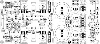
Regarding the power-section, I was maybe unclear - I did not add anything, I just used other values as are found in some manual sections. I have attached the pcb layout with values for reference (this is taken from a freely accessible document on diy-audio-shop.de | Platinen und mehr, hope it is ok to upload here?).
For the attached layout I used 10.000 µF instead of 15.000 and 1.000µF instead of 2.200. The larger values are found on the linked file, the smaller values are found in some parts of the manual. This might be a non-issue, but to someone not familiar with all the inner workings of this amp it is quite a frustrating uncertainty.
Regarding 1, 2 and 3 this helps me a lot and takes the anxiety of soldering the wrong component (correct rating, but wrong "sounding" type).
Regarding the power-section, I was maybe unclear - I did not add anything, I just used other values as are found in some manual sections. I have attached the pcb layout with values for reference (this is taken from a freely accessible document on diy-audio-shop.de | Platinen und mehr, hope it is ok to upload here?).
For the attached layout I used 10.000 µF instead of 15.000 and 1.000µF instead of 2.200. The larger values are found on the linked file, the smaller values are found in some parts of the manual. This might be a non-issue, but to someone not familiar with all the inner workings of this amp it is quite a frustrating uncertainty.
Attachments
Hello Seldon, sorry for not giving you a cordial welcome as a SYMASYM-friend earlier!
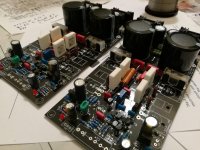
Looking at your images in post 1373: everything looks good so far.
Please take care to get a quad of well-matched 2SK170 as input-differential.
As Andrew has adivsed you: bind a pair of 2SK170 together by means of a shrink hose to thermally couple it.
The capacitors that you have chosen for the backend-PSU are o.k
No reason to be worried!
Just write a post if you have any questions how to go on.
Best regards - Rudi_Ratlos
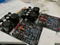
Hi Rudi,
thanks for the welcome. My build has stalled a bit, since I needed to actually work at work instead of doing hobby-stuff
Anyways, I have borrowed a soldering station and am now making progress again in my kitchen. I have finished the small components and am really enjoying this build!
However, of course I have new questions now and thus would be super grateful for any help from you guys.
1. The electrolytic capacitors from the reichelt cart are a wild mix of voltages.. from 63 down to 25. Is there any downside of just ditching them and buying 63V capacitors for everything?
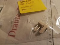
2. The input connector from the cart seems super-cheapo (see picture).. we go through the trouble of gold connectors and expensive cables and then use a 1cent plastic connector on the board? Is this recommended or would it be better to just solder wires directly?
3. My chosen heatsinks are too small. Is it ok to drill the pcb in the indicated spot to use as mounting holes?
thanks for the welcome. My build has stalled a bit, since I needed to actually work at work instead of doing hobby-stuff
Anyways, I have borrowed a soldering station and am now making progress again in my kitchen. I have finished the small components and am really enjoying this build!
However, of course I have new questions now and thus would be super grateful for any help from you guys.
1. The electrolytic capacitors from the reichelt cart are a wild mix of voltages.. from 63 down to 25. Is there any downside of just ditching them and buying 63V capacitors for everything?
2. The input connector from the cart seems super-cheapo (see picture).. we go through the trouble of gold connectors and expensive cables and then use a 1cent plastic connector on the board? Is this recommended or would it be better to just solder wires directly?
3. My chosen heatsinks are too small. Is it ok to drill the pcb in the indicated spot to use as mounting holes?
Attachments
The capacitors need a voltage rating for the voltages they will be exposed to throughout their lives.
Not all of them need to be 63V rated. One, or two may need to be much higher and many could be considerably lower rating.
The plastic is just the support for the pins.
The "connector" is the pin. It should be some plated copper. The plating can be tin, or silver, or gold.
A push fit female will give a gas-tight joint where the female actually touches the male pin.
It's the quality of that gas-tight joint that matters to the signal passing through.
What's on the other side?
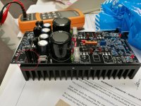
Andrew, thanks again for your help!
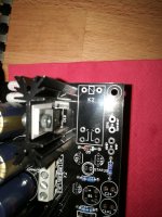
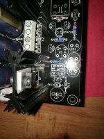
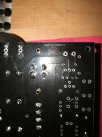
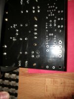
I have in the meantime (impatiently as I sometimes am) soldered the wire directly to the pcb. Here are some pics from the pcb, where I want to drill tomorrow.
I think this should be ok, in worst case I will cut some link to the speaker protection part (which should be fixable with a small wire connection)
Attachments
- Home
- Group Buys
- TO-3 SYMASYM