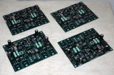
They are less in quality compared what we intended to make
We had some troubles and we had to order less expensive boards..this reduced quality...you had as advantage a reduction in price..but all of us have lost some quality.... i am sorry.
You can clean your board that has a protector varnish that can be diluted ...wipe your board, use alcohol below your board to clean it...you can sand corners if you want using grain 80, 100 or 120 sandpaper.
Islands that have not ground, output or volts input are not thick, these ones you touch your soldering iron into the copper track, at same time you touch the component lead and at same time you melt solder...wait three seconds and observe the solder circle increase the diameter and some flux material spells some small bubbles.
To thick copper tracks you should wait 5 seconds, because thick tracks, or wide tracks, dissipates a lot of heat...use 40 watts soldering iron.
Solder must be shinning...do not move soldering iron tip while soldering...solder may flux by itself.
Of course you know how to solder...but there are other folks that do not know very well..from time to time we have someone facing troubles because cold solder joint (defective solder).
Needing something...just call uncle Charlie:
nanabrother@hotmail.com
Shalom,
Carlos
Attachments
Last edited:
What does FASTON conectors do to the sound?
I hope it is OK to post general questions about building Dx Blame here.
I'm finishing my German Red PCBs and started thinking. I wondered if anyone has objective or empirical information on the efficacy of 1/4 inch FASTON connectors. We spend a lot of money on our loudspeakers connectors, cables and amp output connectors to get them just right. But then we use Faston connectors to connect the PSU to amp PC board, and the PCB to speaker output connectors, etc.
How much influence do these Fastons have on the overall sound? Should we dispose of the Fastons and solder directly to the boards?
Francois
Hi Francois
In terms of sound quality the contact between the female and male faston connectors have no detrimental effect whatsoever in my opinion. It is as good as any plug and socket type connection in the audio system.
However, I think the electrical / mechanical connection between the signal wire and the female crimp socket is much more important. Crimping, unless you have a very expensive and good quality crimp tool, is dodgy and inconsistent. I recommend soldering the wire to the female connector. Either buy sleeveless connectors or remove the plastic sleeve and then solder, then protect with heatshrink tubing.
When possible, always prefere to solder than to use connector
I cannot say about disadvantages of connectors as i do not use them...so...i am not skilled with them.
All i can say is that solder was never a problem to me..... i do imagine connectors can be a problem from time to time..at least mostly often than soldered connections.
We cannot get rid of them....speaker uses... preamplifier uses... signal sources use them....well..... people cannot get rid of them...i can..i use to enter with the audio cable that is soldered directly in the power amplifier input volume potentiometer (entering througth the input connector hole)...also in most of my speakers i do not use connectors...cable goes inside...a node made with the proper audio cable impeach it to go out from the enclosure... a hole is openned back the enclosure to introduce the audio cable... my speaker connectors remains there as decoration.
I do think that direct is always better.... sadly or gladly, my partner, the one produced the board's layout do not think exactly the same as i think about the subject...and we must left room to everybody to exercise the rigth to be free and contribute...he worked hard and wanted to use input and output connectors.... and i let him to use without complain...he deserved that, to put his mark, his style and characteristic in the board he made......but i prefer to have wires and cables soldered directly to the pcboard, and below the pcboard not to have the cabling mess we use to see around...i use to solder directly below the input connectors (for instance) without use it.
But this is personnal...others loves connectors....use them if you want..being carefull they will work fine... some suggestions in the previous post are fine.
regards,
Carlos
Last edited:
From my experience, with signal connections I prefer to solder the cable directly to the board - I don't recomend using conectors such as therminal blocks to signal connection, because they can get loose and make poor connection.
For power supply and outputs, I use fast on terminals, which are, in my opininion, much better than those therminal blocks with screws. As already stated before, you should have a real good crimping tool. If not, you should solder the wire to the female connector. I've never had problems with fast on connectors.
In sum: directly solder signal connections and use fast on therminals to other connections.
The advantage of using fast on connectors is that you can use heavy gauge wiring. If you were to solder the wire directly to the board, you would need a large hole on the board, which is not always possible.
Hi Francois
In terms of sound quality the contact between the female and male faston connectors have no detrimental effect whatsoever in my opinion. It is as good as any plug and socket type connection in the audio system.
.......
Thanks for sharing your experience, RichLund - I will solder the connectors after I crimped them. Thanks also to uncle Charlie and Mitchell.
Francois
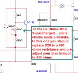
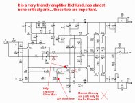
There's an error into the Supercharged bias circuit
R20 should be increased to 680 ohms and the bias trimpot preset goes to 440 ohms.
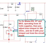
Another image shows the Dx Blame ES, ST and MKII (35 volts amplifiers) preset resistance.
I am sorry, sites are being updated.
regards,
Carlos
R20 should be increased to 680 ohms and the bias trimpot preset goes to 440 ohms.
Another image shows the Dx Blame ES, ST and MKII (35 volts amplifiers) preset resistance.
I am sorry, sites are being updated.
regards,
Carlos
Attachments
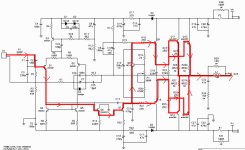
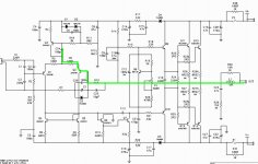
These images will answer you.
Feedback resistors are in the green line.
Audio patch is the red line
There are not too much critical parts...this amplifier sounds great anyway..and accept errors without complain...it is very friendly.
Errors in resistance of plus and minus 20 percent are acceptable...continue to operate fine even this way..also output coil and bypass capacitors.
As bypass capacitors (in paralel with electrolitic condensers) you can use 103, 223,333,473,563,683,823,104,204,224,334,474 and 105.
I am not the one believe capacitor sounds (only errors in value or defective capacitor or wrong polarity sounds)...but if you believe, then search for the best one in your belief.
regards,
Carlos
Attachments
Attachments
Hello,
I've updated the DX website to include a detalied BOM for every board and every DX Blame version.
I also put a wiring diagram for the speaker protection board.
For everyone whose boards haven't arrived yet, please be patient, as postal service is very busy during christmas time.
I've updated the DX website to include a detalied BOM for every board and every DX Blame version.
I also put a wiring diagram for the speaker protection board.
For everyone whose boards haven't arrived yet, please be patient, as postal service is very busy during christmas time.
Another option to adjust the Supercharged
Here you have a video explaining:
YouTube - Adjustment option to the Supercharged - English and Portuguese
regards,
Carlos
Here you have a video explaining:
YouTube - Adjustment option to the Supercharged - English and Portuguese
regards,
Carlos
BLAME vs ALBARRY
I have a 20 year old two Albarry 408 mono Amp (with final driver tip142-tip147) that's getting a little long in the tooth i would like to remove and replace it's internals with a more modern designed Amp.It has a very nice dual secondaries Torodial Transfomer rated at 32+32 650VA a/c which work's out to roughly 40vdc with no load is there any way that this transformer can be ?
I have a 20 year old two Albarry 408 mono Amp (with final driver tip142-tip147) that's getting a little long in the tooth i would like to remove and replace it's internals with a more modern designed Amp.It has a very nice dual secondaries Torodial Transfomer rated at 32+32 650VA a/c which work's out to roughly 40vdc with no load is there any way that this transformer can be ?
ATTENTION! we need to replace the first VAS emitter resistance into the Supercharged
model... see details here:
http://www.diyaudio.com/forums/soli...mkii-supercharged-release-37.html#post2429305
regards,
Carlos
model... see details here:
http://www.diyaudio.com/forums/soli...mkii-supercharged-release-37.html#post2429305
regards,
Carlos
BLAME which model for 42v DC ?
which model has the best performance at 42 volts DC ??
70X12,5 mm the size of the card required few space !!!
model... see details here:
http://www.diyaudio.com/forums/soli...mkii-supercharged-release-37.html#post2429305
regards,
Carlos
which model has the best performance at 42 volts DC ??
70X12,5 mm the size of the card required few space !!!
- Status
- This old topic is closed. If you want to reopen this topic, contact a moderator using the "Report Post" button.
- Home
- Group Buys
- DX BLame ES, ST, MKII, MKII Supercharged Groub Buy Interest