Where is everyone getting their TDA1541A's from?
I got my from ebay, item 220557060865
Wow, the German Post works well 
Hi rtd,
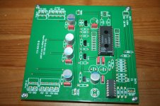
the DGND meets the GP direct at PIN 14.
The only reason for the DC Analog / DC Digital printing is to separate all voltage and GND lines between the TDA1541A
and additional IC´s or circuits (S/PDIF- or USB to I2S converter), witch you could connect to this +5V line.
Best regards,
Oliver
Got mine too, thx.
Few question, where does the DGND meet the top groundplane ? and is there any specific reason you consider 1541 ground as analogue one ?
Thx
Hi rtd,
the DGND meets the GP direct at PIN 14.
The only reason for the DC Analog / DC Digital printing is to separate all voltage and GND lines between the TDA1541A
and additional IC´s or circuits (S/PDIF- or USB to I2S converter), witch you could connect to this +5V line.
Best regards,
Oliver
Wow, the German Post works well
Hi rtd,
the DGND meets the GP direct at PIN 14.
The only reason for the DC Analog / DC Digital printing is to separate all voltage and GND lines between the TDA1541A
and additional IC´s or circuits (S/PDIF- or USB to I2S converter), witch you could connect to this +5V line.
Best regards,
Oliver
Thx... I guess I was not clear enough.
I was talking about DGND for additional IC (you name it DC digital) for which you made separate bottom DGND line. But this separate ground meets the top groundplane. The question is where ?
For the 1541A, i had best results with two separate groundplane tied together under the 1541A , one is considered as analog an the other digital. There are many configuration (see thread in this place), but -15v is refered to the analogue one and -5,+5 to the digital. 100 nF Decoupling is to the analogue ground. Separate PSU is used.
That's why i asked why you apparently consider one solid groundplane (tied at pin 5 and 14) and considered as analogue.
Hi Oliver, I got the boards too.. Thanks.
Just a question, we don't use the +25V on the Salas board? Also, we use 2 power supply boards to create +/-15V and +15V?
Hi toufu,
please look at my post #12. There you could see the power schematic overview and the voltages that are needed.
If your input voltages in the shunt regulatores are a little higher, that´s no problem.
Thx... I guess I was not clear enough.
I was talking about DGND for additional IC (you name it DC digital) for which you made separate bottom DGND line. But this separate ground meets the top groundplane. The question is where ?
Hi rtd,
the DGND for the add. IC´s meets the GP direct at the Wago connector GND pin.
Best regards,
Oliver
Started the TDA board to initially replace the DAC section in my CD960. I want to take the I2S after the SAA7220P/B (already tested on my other 1541 DAC.)
I'm waiting for Takman R's and 3 BG FK's for the TDA rails from Parts connection, the bit decoupling caps and an inductor but this is it so far!
I'm waiting for Takman R's and 3 BG FK's for the TDA rails from Parts connection, the bit decoupling caps and an inductor but this is it so far!
Attachments
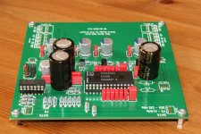
Finished The 5v Salas Reg today and tested with 9v battery's
An externally hosted image should be here but it was not working when we last tested it.
Mine will start with a Burson opamp I/V with CCS for nulling the DC offset (same as my philips CD960), but I will build the Tube-i-zator. I've previously tried many combinations on the outut of a 1541 including oamp I/V into a tube buffer (clone of MF). The best out of the box is the fully discrete I/V and DC servo found in Meridian cdps with this dac.
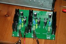
The Takman R's and BG's arrived today S2 won't go in until i've completed any testing!!!!
The Takman R's and BG's arrived today
S2 won't go in until i've completed any testing!!!!Attachments
IRFP9240 alternative???
Guys,
I have a supply issue with IRFP9240. RS, Farnell and several other UK suppliers are out of stock of this device. Mouser have a 32 week lead time, infact Vishay appear not to have any!
Looking at the specs on Vishays website, it appears that there is an identical device for both IRFP9240 and IRFP240 but in a TO-200 package. I have looked at all datasheets and I cannot see any technical differences except the package.
IRFI240 (TO-247) = IRF640 (TO-220)
IRFI9240(TO-247) = IRF9640(TO-220)
Whilst the board is not designed for TO-220, I suspect that the device can be used given the apparent shortage of the IRFP9240.
So currently I have negative regs, but no positive!
Attachments
Oliver, how do we connect the input to the dac? Do you get an optical jack? I don't mind using coaxiel. Where do we buy them and how to connect? Thanks.
Hi toufu,
you need a SPDIF to I2S converter i.e. from Doede Douma or Twisted Pear Audio.
If you want to work with a optical input, you connect the Toslink Module from Twisted Pear Audio in front of the SPDIF to I2S converter.
That´s all. Not really difficult.
Best regards,
Oliver
- Status
- This old topic is closed. If you want to reopen this topic, contact a moderator using the "Report Post" button.
- Home
- Group Buys
- "Reference" TDA1541A DAC with I2S-BUS architecture