I have made some general purpose rectifier boards, which I have offered in the F5 thread , but people might not discover it inside this rather long thread, hence this new thread. 
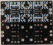
The boards are 38x90mm and you can use all three legged diodes with common cathode (I haven't seen anything else).
You can see a picture of the board here:
http://viller.eu/gb/
Which is also the place to order. As I wrote in the F5 thread, I was getting tired of all the paypal work, so I put together a very simple site to do the tedious tasks for me.
Shipping is done using normal letters without tracking. If you want I can offer insurance, which means I'll refund or resend if the package is lost.
I don't have a BOM for the boards, but here are some suggestions:
Diodes, use any three legged with Anode Cathode Anode legs. Example:
http://www.mouser.com/Search/ProductDetail.aspx?qs=sGAEpiMZZMtEwUVCuofpuJ8elz361Z6mD/We128j0pc=
(you can also use two legged, but then you need to bend the legs slightly)
Heatsinks, if you want to use onboard sinks use these:
http://www.mouser.com/Search/ProductDetail.aspx?qs=wT7LY0lnAe0UzSGKJGAHIA==
For the snubbers (resistor and capacitor) you can use 100ohm and capacitors in the 20-100nF range.
And of course you will need to buy 4 of each for one board.
Re: rectifier boards
Yes, they are intended for 1/4 watt resistors. The holes are for a capacitor (in small scale applications), but unfortunately the holes got too small for snap-ins.
alazira said:Hi,
I received the boards, thanks. What are those two holes in the very center for? Also, are 1/4 watt resistors ok. I also have 2w kiwame carbons that I can use if I mount soilder style.
Yes, they are intended for 1/4 watt resistors. The holes are for a capacitor (in small scale applications), but unfortunately the holes got too small for snap-ins.
Christian,
I hope you are enjoying "summer in the city" and have eaten in Chinatown by now........MMMMMMMMmmmmmm.
I have a question about the center capacitor, it would be #5, (circled in photo)
What value should this be? same as the other 4?
Also it was not in your schematic.
It is a Very Cool looking board, btw.
Ron
Attachments
Thanks for the fast response Christian,
Got it.
Hey, You gotta eat don't you?
Find the "Hole in the wall" (small Owner run shop) restaurant that has only a few tables and sparse decor. If your lucky they will speak a little English. OOOooooHhhh man, fresh cooked veggies on the spot, hand made noodles and soups, sticky rice.......
I'll eat vicariously through you........I don't need the added pounds.
Ron
(I won't forget I owe you a beer )
)
Got it.
Hey, You gotta eat don't you?
Find the "Hole in the wall" (small Owner run shop) restaurant that has only a few tables and sparse decor. If your lucky they will speak a little English. OOOooooHhhh man, fresh cooked veggies on the spot, hand made noodles and soups, sticky rice.......
I'll eat vicariously through you........I don't need the added pounds.
Ron
(I won't forget I owe you a beer
)eemmmm, I gota nutha question
Christian,
Sorry to bother you again.
On the rectifier boards, the locations for the snubber caps are not marked + / - , pretty shure it makes a difference. As the caps I have are not nonpolarized. Help me out will ya please??? I've tried to figure it out, but no joy. I'm too uneducated...... Sad.
Thanks,
Ron
Christian,
as per your recommendation .068uF , I thought the caps were used as a buffer after the rectification to smooth out the remaining sinosidial wave. Or are they used to prevent the "ringing" of the diodes closing?
I am using MUR860 that I got from Jackinnj's website.
Should I just forget the caps and Rs and just use the diodes?
Thanks for helping me learn electronics.
Ron
Renron said:Christian,
as per your recommendation .068uF , I thought the caps were used as a buffer after the rectification to smooth out the remaining sinosidial wave. Or are they used to prevent the "ringing" of the diodes closing?
I am using MUR860 that I got from Jackinnj's website.
Should I just forget the caps and Rs and just use the diodes?
Thanks for helping me learn electronics.
Ron
Yes, they are there for preventing ringing - so unless you have something else lying around, you might be better of leaving them out.
Going by Hagerman's snubbers article, it looks like you only need one resistor and one capacitor per bridge, rather than one per diode. Could your board accomodate this?
As an aside, he explains the calculations to determine the optimal values for R and C in the snubber. I have not been able to determine if you could potentially be worse off choosing non-optimal values for these than leaving them out.
Ron, any capacitor used in this application will be small enough (well under 1 uF) that electrolytic capacitors aren't even a consideration.
Cool article - I just skimmed it briefly, but it seems like he is looking at a single diode (half wave). He tries to justify that his calculations holds for full wave rectifiers too and he is probably right.
But I'm quite sure you still need a snubber per diode and in a normal full wave bridge you have four.
But I'm quite sure you still need a snubber per diode and in a normal full wave bridge you have four.
I too read his article entitled, "Calculating Optimum Snubbers" thanks for the tip!
Well written as even I understood his theory and from my use of PSUDII confirms what he states.
This stuff is cool........
Grenert,
Are you saying that because the capacitance is so small , .068uF that it would be OK to use electrolytics as the caps in a snubber network?
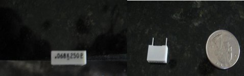
The caps I have look like little white plastic blocks with 2 pins out of the bottom. I can post a pic if that helps.
Thanks a lot guys, it's greatly appreciated.
Ron
Well written as even I understood his theory and from my use of PSUDII confirms what he states.
This stuff is cool........
Grenert,
Are you saying that because the capacitance is so small , .068uF that it would be OK to use electrolytics as the caps in a snubber network?
The caps I have look like little white plastic blocks with 2 pins out of the bottom. I can post a pic if that helps.
Thanks a lot guys, it's greatly appreciated.
Ron
Renron said:Are you saying that because the capacitance is so small , .068uF that it would be OK to use electrolytics as the caps in a snubber network?
The caps I have look like little white plastic blocks with 2 pins out of the bottom. I can post a pic if that helps.
No, I'm saying that at such low capacitances, electrolytics are not needed, desirable, or even available. Your description of a "plastic block" sounds like a film capacitor, which should be fine. Film capacitors are nonpolar, hence no need to mark + and - on the board.
Grenert,
Thank you for taking the time to answer my (probably) foolish question. I know from hanging around this website long enough that even though some of us (me) ask to be spoon-fed information, it is better for us to figure it out on our own.
I too think what I have in my surplus bag of stuff, is a film cap.
Thanks.
I found some other stuff too, a 100V poly cap from Panasonic which, after I looked up the specs. led me to a table of "Permissible Voltage (RMS) in Alternating Current Corresponding to DC Rated Voltage". This particular unit I have is rated for 63V RMS Alternating Current. Happy camper having learned quite a bit today on power supplies and how complicated they can be. I had no idea capacitors other than nonpolarized could be used safely in SOME A/C applications.
Thank you both VERY much.
Appreciative,
Ron
Thank you for taking the time to answer my (probably) foolish question. I know from hanging around this website long enough that even though some of us (me) ask to be spoon-fed information, it is better for us to figure it out on our own.
I too think what I have in my surplus bag of stuff, is a film cap.
Thanks.
I found some other stuff too, a 100V poly cap from Panasonic which, after I looked up the specs. led me to a table of "Permissible Voltage (RMS) in Alternating Current Corresponding to DC Rated Voltage". This particular unit I have is rated for 63V RMS Alternating Current.
Happy camper having learned quite a bit today on power supplies and how complicated they can be. I had no idea capacitors other than nonpolarized could be used safely in SOME A/C applications.Thank you both VERY much.
Appreciative,
Ron
- Status
- This old topic is closed. If you want to reopen this topic, contact a moderator using the "Report Post" button.
- Home
- Group Buys
- Gb: Rectifier boards