I thought about changing the footprint to be correct for ZTX, but as you say, people don't read too much so I was afraid of causing yet more confusing.
Sure, I had the same issue when I first tried to learn a bit about this, just enough to do a hardwired F5
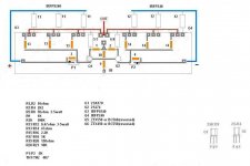
Even if I might use BC###, I chose to figure the layout as pr orinigal schematic, as I found that less confusing
But I would suggest to do a board especially made fore hardwired outputstage
One advantage would be easy to adapt to different heatsinks
Other would be learning
Third, it might be easier to implement mods along the way
And yeah, always wanted to do a hardwired outputstage and thought it looked cool
I know, some may not like that at all
Attachments
Last edited:
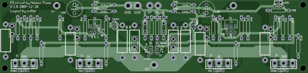
Here is the final layout - unless someone points out an error. I'll offer a free set of pcbs to the first one who spots a circuit error (not just a silkscreen bug)! ")
I have added holes for caddocks - it didn't make the board prettier, but since I always recommend tech-diy for parts it would make the most sense if the boards were fully compatible. I have also changed the ztx footprints according to the suggestions I got here on the thread.
Tinitus, I like your idea, but I think this F5 will stay on one board. You should have a look at the BA-1 and BA-2 stuff - that's versatile!!
Attachments
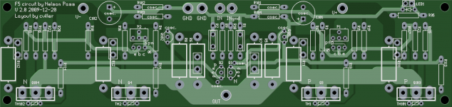
Might be a good idea to mount R12,R13 a trifle north of the adjacent mounting holes -- if you use a pan-head screw it might make contact w the resistor (or MOSFET). The Panasonic 3W resistors are an R0617 profile.
The Caddock MP30's, unless heat-sinked, will only handle 2.25 watts. Just want everyone to be aware of that. Here's the datasheet: http://www.caddock.com/Online_catalog/Mrktg_Lit/MP9000_Series.pdf
The Caddock MP30's, unless heat-sinked, will only handle 2.25 watts. Just want everyone to be aware of that. Here's the datasheet: http://www.caddock.com/Online_catalog/Mrktg_Lit/MP9000_Series.pdf

npapp, I have ordered more boards than there was signed up for, so you can order as many as you like on GB order page for cviller
You can also see the gb list here: Group Buy status page
You can also see the gb list here: Group Buy status page

I asked the company if they could tell me when they would ship and they said they would. I have ordered from them three times before and this how they usually do - not much communication and then suddenly there is a package with some really nice boards!
I ordered right before Christmas, so I'm unsure of exactly how many business days have gone by so far.
I ordered right before Christmas, so I'm unsure of exactly how many business days have gone by so far.
Last edited:
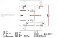
I was thinking more in terms of something like this (just like borbeley does). Just need to simulate if it works in this application.
A good way to handle this is to provide an area on the board that is basically plated trough holes in a matrix (12 x 12 for example) - like a proto board - so that those who want to put in a cascode circuit can brew up their own, as they wish, proto style... simple enough.
Just an idea...
_-_-bear
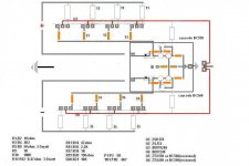
Speaking of which - could you please post again or link again the final schematic and the layout?
I trolled around and am quite unsure what that is - the last i saw was a pdf of a proposed dual jfet cascode input...
I'll deal with whatever it is, but it would be good to clear on it... I'm confused anyhow... but that is easy for me!
_-_-bear
I trolled around and am quite unsure what that is - the last i saw was a pdf of a proposed dual jfet cascode input...
I'll deal with whatever it is, but it would be good to clear on it... I'm confused anyhow... but that is easy for me!
_-_-bear
BTW: I'm a little bit worried about "regular stuff"...... don't worry about this extra stuff.
Any news?
Cheers,
- Status
- This old topic is closed. If you want to reopen this topic, contact a moderator using the "Report Post" button.
- Home
- Group Buys
- Gb: F5 Pcb