I've been looking for the proper way to wire up the two rectifiers. Seems to me that I should connect the minus term of the rectifier going to the positive side of the PCB to the plus terminal of the other rectifier, but I find no information on that. I don't doubt that it is there - but the search function of this site is not usable.
I am a newbie, so I cannot answer you with confidence, but I found a lot of info on in this thread
PSU for beginners
and, just copying, I was able to build a PSU for a phono pre
Renato
northernsky said:
I am a newbie, so I cannot answer you with confidence, but I found a lot of info on in this thread
PSU for beginners
and, just copying, I was able to build a PSU for a phono pre
Renato
That diagram shows the ground connected together at the rectifiers. I'm not certain but I would think it's better to connect them all together at the point of the star ground.
F5 up and running
My F5 has two heat sinks about 8x5 inches by 2.25 inches thick, but still they get too hot. So I put 12v fans on them running at 5 volts.
Heat sinks get up to 48C after 1 hour and the MOSFETS themselves when directely probed are almost no hotter, 50C or so within 1 degree. Bias across each of the 0.47 ohm emitter resistors turn out to be (after 1 hour of no input or output) set at .65 volts instead of the .59 volts in the article.
Due to the fans I am able to get a little higher bias, not on purpose really but this is just how it worked out with my settings, and < 20 mV DC offset. Not too bad.
Any problems with this before I close it up and run it for a few weeks?
Re: F5 up and running
Sounds good, but have you tried to check if the temperature stays within safe range when the lid is on?
It is preferable to do the final adjustments of bias and dc after one hour, or when the amp reaches steady state operating temperature.
lgreen said:My F5 has two heat sinks about 8x5 inches by 2.25 inches thick, but still they get too hot. So I put 12v fans on them running at 5 volts.
Heat sinks get up to 48C after 1 hour and the MOSFETS themselves when directely probed are almost no hotter, 50C or so within 1 degree. Bias across each of the 0.47 ohm emitter resistors turn out to be (after 1 hour of no input or output) set at .65 volts instead of the .59 volts in the article.
Due to the fans I am able to get a little higher bias, not on purpose really but this is just how it worked out with my settings, and < 20 mV DC offset. Not too bad.
Any problems with this before I close it up and run it for a few weeks?
Sounds good, but have you tried to check if the temperature stays within safe range when the lid is on?
It is preferable to do the final adjustments of bias and dc after one hour, or when the amp reaches steady state operating temperature.
labjr said:
That diagram shows the ground connected together at the rectifiers. I'm not certain but I would think it's better to connect them all together at the point of the star ground.
I wouldn't connect the unfiltered gnd to the star gnd, but whether you connect the gnd on the bridges or on the first capacitor bank makes very little difference.
here how I connected gnd wires http://www.diyaudio.com/forums/showthread.php?postid=1810368#post1810368
I have to say that I got a lot of buzz
could you suggest better gnd wiring
I have to say that I got a lot of buzz
could you suggest better gnd wiring
Re: Re: F5 up and running
All set, this is after 1 hour with the lid on and no input or output. I have snaked the probes into the case and can view bias with the amp running and the lid on. I can snake a thermo probe onto the heat sinks through the lid grill and check sink temps easily. After 1 hour I remove lid and immediately check temps of the MOSFETs themselves within about 10 seconds.
The bias does tend to creep up even after 1 hour, perhaps I have not reached equilibrium? I will try for 2 hours.
cviller said:
Sounds good, but have you tried to check if the temperature stays within safe range when the lid is on?
It is preferable to do the final adjustments of bias and dc after one hour, or when the amp reaches steady state operating temperature.
All set, this is after 1 hour with the lid on and no input or output. I have snaked the probes into the case and can view bias with the amp running and the lid on. I can snake a thermo probe onto the heat sinks through the lid grill and check sink temps easily. After 1 hour I remove lid and immediately check temps of the MOSFETs themselves within about 10 seconds.
The bias does tend to creep up even after 1 hour, perhaps I have not reached equilibrium? I will try for 2 hours.
Too many grounding wires. I can see two ground loops.max426 said:Here is a very nice drawing of power supply and grounding, scroll to the end of the file. Thanks to Jan Dupont.
Jim
The F5 needs only one connexion between PCB and star ground.
Re: Re: Re: F5 up and running
Mine takes two hours or so to reach equilibrium. I still set the final bias at about .590-.600 and make sure it doesn't drift up or down to much over another 4-8 hours untouched running idle with no speakers connected. I set this with a room temp of 74 degrees to compensate for summer weather.
lgreen said:
All set, this is after 1 hour with the lid on and no input or output. I have snaked the probes into the case and can view bias with the amp running and the lid on. I can snake a thermo probe onto the heat sinks through the lid grill and check sink temps easily. After 1 hour I remove lid and immediately check temps of the MOSFETs themselves within about 10 seconds.
The bias does tend to creep up even after 1 hour, perhaps I have not reached equilibrium? I will try for 2 hours.
Mine takes two hours or so to reach equilibrium. I still set the final bias at about .590-.600 and make sure it doesn't drift up or down to much over another 4-8 hours untouched running idle with no speakers connected. I set this with a room temp of 74 degrees to compensate for summer weather.
samoloko said:here how I connected gnd wires http://www.diyaudio.com/forums/showthread.php?postid=1810368#post1810368
I have to say that I got a lot of buzz
could you suggest better gnd wiring
I think you can remove the first two rungs of your copper ladder. then attach the rca ground-speaker ground and ground (one only) from PD boards to this same place. Then attach Thermistor to copperplane and to Power ground. Then from outlet ground run a copper wire to chassis (I forget this originally, and got a buzz).
If you lift power ground and still get buzz, its a signal problem. if you lift short inputs and still get buzz, the star ground is suspect.
I have two F5's biamp'd. Both are setup this way with proper grounding and no buzz.
Sorry if some of this has been discussed already. Just trying to help.
thx for help
would you please check the attached scema and tell me If there Is something wrong
__________________________________
Moderator's note:
apparently this diagram is not correct.
See
http://www.diyaudio.com/forums/showthread.php?postid=1815684#post1815684
would you please check the attached scema and tell me If there Is something wrong
__________________________________
Moderator's note:
apparently this diagram is not correct.
See
http://www.diyaudio.com/forums/showthread.php?postid=1815684#post1815684
Attachments
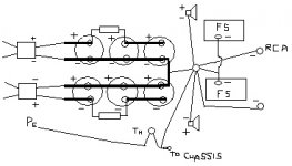
I see some points i would do differently:
I would connect each pcb ground separately to star ground.
I would connect rca ground directly to pcb (instead of star ground) because the PCB grounding point is close to input connection one. I would use the shielding part of the shielded input cable to do this.
I would too connect caps together into a starring manner.
You mustn't have hum this way.
But the best (royal) way is to use two transformers ( or one with four secondary windings) and make a dual mono or two monoblocs.
...Are you shure that hum is produced at F5 level? It has such a low gain.
samoloko said:thx for help
would you please check the attached scema and tell me If there Is something wrong
Samoloko -
I have it connected all to the power supply rail, but this doesn't look any different really. The shieleded wire I would run as well, but only connect the ground to ground at RCA. Other side open.
More importantly, I would connect to the chassis after the thermistor at PE point. that keeps some resistance before going to ground, keeping ground loops a little at bay.
Tea-Bag said:
1. I have it connected all to the power supply rail, but this doesn't look any different really. The shieleded wire I would run as well, but only connect the ground to ground at RCA. Other side open.
2. More importantly, I would connect to the chassis after the thermistor at PE point. that keeps some resistance before going to ground, keeping ground loops a little at bay.
1. The shield in shielded wires must be connected at both ends - otherwise you lose the shield and get an antenna instead.
")
2. Good point.
This grounding scheme:
http://viller.eu/audio/2009jan_gbf5/P1070474_wiring1.jpg
has worked very well for me many times. But it requires sane gnd routing on the amplifier boards.
1. The shield in shielded wires must be connected at both ends - otherwise you lose the shield and get an antenna instead.
Not if pcb end is connected to star ground. But if both ends connected plus ground rca connected to star ground thats create a ground loop.
would you please check again
-------------------------------------------------------------
Moderator's note:
apparently this diagram is not correct.
See
http://www.diyaudio.com/forums/showthread.php?postid=1815684#post1815684
-------------------------------------------------------------
Moderator's note:
apparently this diagram is not correct.
See
http://www.diyaudio.com/forums/showthread.php?postid=1815684#post1815684
Attachments
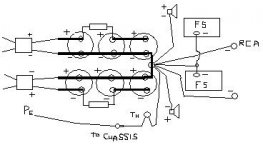
bobodioulasso said:
Not if one end is connected to star ground.
I thought an antenna it would be only on input side. I have used shielded wire on F5, and seems fine. I have done both direct to star ground and to boards with no real different results. I think the PS here can be problematic if not done right.
In general bi-amping or monoblocks for L and R seem more problematic in my experience in dealing with ground loops. Keeps one thinking.

- Status
- This old topic is closed. If you want to reopen this topic, contact a moderator using the "Report Post" button.
- Home
- Group Buys
- Gb: F5 Pcb