I still have Jens board too and that's a very sturdy/thick board. Does anybody have the build procedure for that amp? I might try to build it when I get a chance.
I don't remember a build procedure having been put together. Have you poked around the threads about it?
Which version is it? There were several.
Jens always preferred thicker boards with much thicker copper, such as 3oz.
How thick is that board?
I saved a lot of info about most of that stuff and have re-created the 5 pairs version layout, since Jens never wanted to share the eagle files. So I guess it should be pretty straightforward to put out gerbers and make more of that version if some wanted it.
Nice boards still available?I still have Jens board too and that's a very sturdy/thick board. Does anybody have the build procedure for that amp? I might try to build it when I get a chance.
That was a very impressive math heavy “manual”, I don’t think it discussed how to build it but had a lot of very complicated math analysis, never before seen except in a graduate level partial differential equations engineering course ") to show how the power dissipation and heatsinks should be sized.
to show how the power dissipation and heatsinks should be sized.
I did not see the component values given anywhere, so I don’t think this is a build manual.
to show how the power dissipation and heatsinks should be sized. I did not see the component values given anywhere, so I don’t think this is a build manual.
You mean this:
Leach Amp Plans - Part 3
Perhaps that could have been put into the above pdf if it is to be called a manual. Not a big deal, just misleading use of the term “manual”.
Looks like an interesting amp though.
Leach Amp Plans - Part 3
Perhaps that could have been put into the above pdf if it is to be called a manual. Not a big deal, just misleading use of the term “manual”.
Looks like an interesting amp though.
That was a very impressive math heavy “manual”, I don’t think it discussed how to build it but had a lot of very complicated math analysis, never before seen except in a graduate level partial differential equations engineering course
I did not see the component values given anywhere, so I don’t think this is a build manual.
Yeah, Jens did some solid work here. I have a BOM too, but yes as Tony says, the info to build this is actually on this thread and others on the forum.
Attachments
If anyone is interested ...
I come across a stash of the Jens PCBs a while back. I bought them with the intention to build but never got around to doing that. Life got in the way or I saw something shiny, who knows. I am certain that I have output devices as well. Please message me if anyone is interested. I'd hate to see them go unused.
Carl PM sent
Does anyone know what the width of the tracks are on Jens 6 & 10 OPT boards?
I have been able to open the Delta Audio gerber files and convert them to dxf, then load them in a CAD program to delete the 10 thousand or so lines used for gerber photo plotters this will allow me to import the modified dxf files in DesignSpark PCB to be able to print them as PDF fas well as export them as gerber RS-247-X files to be milled on my new 3-axis mini CNC.
I have been able to open the Delta Audio gerber files and convert them to dxf, then load them in a CAD program to delete the 10 thousand or so lines used for gerber photo plotters this will allow me to import the modified dxf files in DesignSpark PCB to be able to print them as PDF fas well as export them as gerber RS-247-X files to be milled on my new 3-axis mini CNC.
I found this leach at buildaudioamps.com project 59. it utilizes 8 output devices.
Link is here.
Project 59 – BuildAudioAmps
I believe the guy is a member here.
Link is here.
Project 59 – BuildAudioAmps
I believe the guy is a member here.
Attachments
I found this leach at buildaudioamps.com project 59. it utilizes 8 output devices.
Link is here.
Project 59 – BuildAudioAmps
I believe the guy is a member here.
Not the most effective thermal sensing scheme. Can be improved upon. And why the separate smaller heatsinks anyway?
In the original Leach amp, the 4 diodes were inserted into the heatsink. Jens came up with the little PCB to bolt the diodes against the heatsink. Works fine.Not the most effective thermal sensing scheme. Can be improved upon. And why the separate smaller heatsinks anyway?
I am ready for the measurements to get this done and submitted to Jens for his review.
This conversion will allow for several different mfg options.
I am doing this as a 5 fold result driven project.
I am unsure but remain hopeful that Jens will allow for #3 & #4.
1) All Jens design files except what is found on Delta Audio Wayback Machine website was lost when his Hard Drive crashed.
2) Users to download and submit the original Delta Audio Jens designed .plt photo plotter gerbers to a boardhouse.
3) Users to be able to download and submit CNC gerbers to a boardhouse that uses CNC routers. (using my CNC and finish with multicolor soldermask/silkscreen paint).
4) Users to be able to download .bmp/.pdf/.jpg for their own DIY thermal transfer and chemical etching.
5) My gift back to my DIYaudio community.
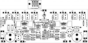
This is what I have been able to do so far.
Notice the photo plotter arperature tool paths are center of all tracks. Some tracks/pads/via's are actually either touching (mostly due to line width) or actually connecting with adjacent tracks/pads/via's.
I used the CAD program to measure the distance between some of these super close proximity pads in the .dxf file and some of the isolation distances are .01mm!
This might be fine if someone or a boardhouse uses the photo plotter gerbers and presensitized boards, but definitely not far enough apart using a minimal .1mm routing bit or DIY thermal transfer & chemical etching.
Also, the wheel arperature file does not readily have the width of the tracks. It is simply a file that specifies the diameters & shapes for all of the pads.
The tool file which has the diameters of the holes will be cross referenced with the drill file x,y locations.
Attachments
I am ready for the measurements to get this done and submitted to Jens for his review.
How do you think Jens will review this? I don't think he has been on the forum for years now. Maybe he doesn't even read any posts nowadays.
What makes things more difficult in picking up after Jens, since he pretty much disappeared from the forums, is the fact that he never wanted to share his original eagle design files, by fear that he would be giving out his eagle software serial number in the process, because he was under the impression that info was present in the files.
But that's not the case at all, so he was bigly wrong about that. I have been digging into such files many times over the years to manually fix issues caused by eagle when it didn't handle the back annotation properly, so then design files would end up unusable from that point. So I have many times done editing manually outside of eagle to fix things, and so I know what info about eagle is present in the files, and that is the eagle version, nothing more.
So he had no valid reason to be scared about his serial number being shared.
But anyway, from all the data from back then, when he was sharing some of the things, I was able to re-create pretty much the same designs in eagle, from scratch. And since, I've made several iterations of improvements. Plus I've done a fair amount of tweaking on the way the ground planes were done, to make at least one plane more intact, so it's more of a real ground plane, with far fewer breaks in it.
The most significant improvements I've been after, were a more sensible thermal sensing scheme. Although I would like to move away from individual diodes altogether, I kept that principle but aimed for a better thermal sensing, not just about how it's "joined" but rather how long the thermal lag is, due to the overly long distance between the sensing diodes' junctions and the power devices' junctions.
For that build as mentioned in post #1572, the thermal joining can't be very good, with only small strips of each diode's case being pressed against the heatsink. Not a very efficient thermal joining. Not to mention the long thermal lag due to how far away from the power devices that sensing board is placed.
I made a variant of the improved version based on Jens' design, with smaller separate sensing boards, which are mounted right on top of power devices. This reduces the number of thermal junctions, by a lot, plus the thermal lag can hardly be any shorter, being that close to the power device's junction..
- Home
- Group Buys
- Jens Rasmussen Leach clone group buy