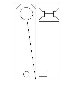
Hi, super-noob here. I am interested in building a pair of bipole towers using the TB w4-1320 drivers. I've pretty much settled on a folded ML TQWT due to the simplicity of the construction.
I've put together a little illustration of what I'm looking for, However, I don't have the faintest idea of how to calculate the dimensions for this kind of design.
I've done simple bookshelves and sealed woofers for my car before, but this seems a little bit out of the range of those online calculators that i usually use.
Would anyone out there like to enlighten me on how i could calculate what i need? I see a lot of reference to MathCad, which i assume is some kind of custom program... but I'm not sure if this is what i need? thanks a lot in advance.
Go to Martin's Website All of the information is there. You can also check out Bob Brine's website for some advise also.
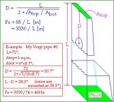
I'm definately not the best person to answer your questions, not calculate your box for you, but I can hopefully help point you in the right direction. Also if I understand the voigt pipe, look that up. If that is right, what you have designed is a folded voigt pipe essentially. Below should help to design a voigt pipe.
Good Luck,
Josh
Attachments
wow, that was a lot of info...still trying to digest.
I guess it was too much to hope for to find some calculator where i can plug in the driver T+S parameters and some cabinet variables to output some final dimensions.
Well, as they say: Garbage in, Garbage out.
Time to do some homework.
some feedback on the general feasibility of the design would be nice, or the opinion of someone who built something similar.
Where can I find Bob Brine's website?
Bob's site: he has some excellent articles there that will help you understand the design proceedure with Martin's mathCad worksheets.
http://www.geocities.com/rbrines1/
The Worksheets are actually easy to use -Martin's done all the math for you. You just need the T/S parameters and to specify the dimensions.
So = the top (sealed end) of the line.
Sm = the far (or end with an opening of the line).
Mass loading means the end of the line is constricted, with a port -the air mass provides additional loading to the quarter waves the cabinet is designed to utilise.
The rest is fairly self-explanitory -driver positioning, stuffing desnsity etc. With a bipolar setup, Sd (the driver surface area)doubles, Vas doubles, impedence halves (if they're wired in parallel).
As for what's there at present, the basic geometry is fine, but for the love of heaven, don't use So=0 (i.e. don't bring the top, sealed bit of the line) to a point. Except in very specific circumstances, this is A Bad Idea. I've actually already posted the dimensions for an unfolded bipolar pipe using these drivers a couple of days ago -see my last post here:
http://www.diyaudio.com/forums/showthread.php?s=&threadid=66576
Just fold in half -it'll work just the same. I provided a MathCad generated response curve for it a few posts before.
Hope some of this helps
Scott
OK so i think i have a handle for the basics on the design theory. Quick question: Where did you get the 7Sd multiple from?
With 2 drivers, that works out to about ~123 sq inches for Sm. Along with a ~16inch So and including a bit of 3/4 MDF, that would make my inside bottom cabinet surface area about 1 sq ft. My subwoofer is 12x12x12 on the inside and that thing is massive!
What I'm trying to get at: is there any way to reduce the interior footprint on this project to around 8" x 10"?
with the 7:1 Ratio, an 8" width would require a depth of 17"....That is unacceptable for various reasons...(mostly WAF)
8" +3/4 + 3/4 is already a 9.5" wide cabinet....thats as far as i'm willing to go. Ditto for anything over 12" in depth....
BTW you guys have been very helpful so far in pointing things out - thanks
The Sm=7Sd came from me running a MathCad sim for someone else wanting to use these same drivers in a bipolar design a couple of days ago. I used it because it's the optimum dimension for this configuration. You can reduce Sm to 5Sd at the sacrifice of a somewhat rougher response. Any less, and it'll be crippled; don't go lower is my advice. They will need either a 2.25ohm resistor in series with the hot lead (thank you GM), or, simpler, a run of narrow gauge cable to provide the correct damping and bring the bass into line. Just what gauge will depend on your amp, and how long a run to the speakers you have. 24AWG magnet wire or similar would be a good place to start. I've tried to come up with a bipolar straight MLTL in MathCad for these drivers too -nothing worth building yet though I'm afraid -I'll let you know if I come up with anything that will work well.
Best
Scott
Best
Scott
Greets!
You're welcome!
With an 80"^2 CSA and 2.25 ohms series R, this straight ML-TL doesn't look too terribly shabby compared to your ML-TQWT, and the driver's up closer to ear height as a bonus") :
:
L = 55"
zd = 19.375"
zp = 40"
rp = 1.5"
lp = 1"
stuffing = 0.25 lbs/ft^3 down to the bottom
GM
You're welcome!
With an 80"^2 CSA and 2.25 ohms series R, this straight ML-TL doesn't look too terribly shabby compared to your ML-TQWT, and the driver's up closer to ear height as a bonus
:L = 55"
zd = 19.375"
zp = 40"
rp = 1.5"
lp = 1"
stuffing = 0.25 lbs/ft^3 down to the bottom
GM
Quick translation:
-Line length: 55"
-Top and bottom are 80 square inches
-Driver centre mounted 19.375" from the top of the enclosure
-Port mounted 40" from the top of the enclosure (that's quite a way up -no criticism BTW, just an interested observation, I've learned something new again, which is great!)
-Port dimensions: 3" wide x 1" deep.
-Stuff the cabinet with something like Dracon, 0.25 lbs to the cubic foot.
-Place a 2.25 Ohm resistor in the positive lead from the amp going to the speaker. Alternatively, you could just use a higher resistance speaker cable. Go for it -this is good!
Best
Scott
Scottmoose said:
-Place a 2.25 Ohm resistor in the positive lead from the amp going to the speaker. Alternatively, you could just use a higher resistance speaker cable. Go for it -this is good!
Or use SE tubes! =D
Is everyone working from TB's spec sheet or have you derived the T&S parameters? My pair are breaking in using a cabinet sized for the 657s and sound incredibly musical (if without bass) in the company of the above mentioned TBs and Jordans. Nice driver. Cold out of the box one measured an Fr of 75 Hz, the other 85 Hz. Just wondering what you're all finding.
Fs 81.839996, Qms 2.121518, Qes 0.674866, Qts 0.511997
Mms = 4.18
Cms = .00090389
Vas = 4.11 liters
Fs 75.559998, Qms 2.049201, Qes 0.601340, Qts 0.464911
Mms = 4.13grams
Cms = .001074
Vas = 4.8 liters
This is what I got after break in for my pair. Mass added technique, for Vas
Joe
Mms = 4.18
Cms = .00090389
Vas = 4.11 liters
Fs 75.559998, Qms 2.049201, Qes 0.601340, Qts 0.464911
Mms = 4.13grams
Cms = .001074
Vas = 4.8 liters
This is what I got after break in for my pair. Mass added technique, for Vas
Joe
- Status
- This old topic is closed. If you want to reopen this topic, contact a moderator using the "Report Post" button.
- Home
- Loudspeakers
- Full Range
- W4 1320 bipole...dimensions?