Bipolar MLTL Speaker with FR125S/WR125S
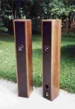
I recently completed a bipolar MLTL using the CSS FR125S as the front driver and the WR125S as the rear driver. The connection of the two drivers in each box is in phase so that a bipolar field (forward and rear radiation) is created.
The box duplicates Greg Monfort's (GM) design that he describes in his posting:
http://www.diyaudio.com/forums/showthread.php?postid=672120#post672120
I built Greg's MLTL design that is the 45 Hz and +/- 1 dB. The drivers are located 14" internally below the top of the box. I lightly stuffed the top of the box (from below the drivers). The port tube is on the rear of the speaker and just above the bottom floor of the MLTL line. The drivers are positioned about 33.25" above the floor. I located the terminal plate in a cavity at the bottom of the enclosure. The cavity spaces the drivers upward to their listening position plus allows room to add mass to stabilize the box. Also any contouring components, if needed, could be located in this cavity.
The enclosure was constructed of 0.75" thick MDF panels for the baffle, rear, and bottom of the box with walnut top and side panels. Internally, three braces are used to stabilize the structure. The outside dimensions of the enclosure are 48" high, 7.5" wide, and 8.75" deep.
The sound of these speakers is very nice indeed with more bass than you would expect from the volume. The four drivers do a nice job in adding low end impact to your music. The frequency response of these drivers is very flat across the band and this design retains this benefit. More important these speakers exhibit the coherent nature that we have come to expect from quality full range drivers without a crossover.
The bipolar drivers in these speakers necessitate that you position them away from the wall--I'm using 3 feet in my room. Their bipolar nature of this speaker does two things that you will notice to your listening. First, you'll notice a little ambiance as sound energy is reflected from the back wall in the room. In this case ambiance is a good thing--more apparent during say a newscast--but with not an issue when you listen to music. Secondly, the soundstage is wider than you'll have with just a single front firing driver. One very minor disadvantage to the bipolar nature of these speakers is that the stereo image is a little more diffuse than with direct firing drivers. In my opinion having a wider sweet spot is an advantage in my book.
The FR125S full range driver does an excellent job across the frequency band and for most music you'll not miss any extra airyness that a separate tweeter might contribute.
Bottom line is that this is a very simple design yet it yields great results. A lot of bang for their cost.
Jim
Attachments
Last edited by a moderator:
Al,
It is hard to compare the CSS FR125S as a driver directly versus the Jordan JX92S as my implementations are so different. My initial impressions are that the JX92S is more sensitive (say a couple of dB or so) while the FR125S has a smoother response in the upper octave than the Jordan. The Jordan may have a slightly lower F3 point on the low end but not by much but that would depend on how you design the box (bass reflex, MLTL, etc).
The bipole configuration by its nature eliminates the baffle step compensation issue so in practice the speaker implementation of a bipolar configuration would be more sensitive than one that needs a BSC. I am also impressed with the amount of bass that the MLTL has with the FR125S and WR125S. So much bass that only a bass head would wish for a subwoofer for listening to most musical programs.
Bottom line is that even with 2 FR125S and 2 WR125S drivers in these boxes the biploar speaker design would still be lower driver cost than a pair of JX92S drivers.
Thus what is not to like about this bipolar design? I guess you could fault the 4 ohms impedance or such but for its bang for the buck is high if your amp can cope with the impedance.
Jim
Thanks Jim
I was wondering if you got to list to them in say a .25cft cabinet just for fun.
I am sure of the design you have done will have a few others looking this way as well but like you said the 4 ohm is the only low side.
Like the rear firing driver Dan did this on the Apex design and helps out a lot for larger mid presence.
The FR in a .25cft cabinet as we have done is a good small compact speaker that will fill the needs of most as you have said.
Good work Jim
Hi Jim
I am also considering Greg's design, but I would like to build a triagularly-shaped speaker (to be used as rears in an HT set-up). For a triangular enclosure the two short sides will be ~9.35” and the long side ~13.22” long (all dimensions internally, and the short sides at 90 degrees to each other). I am also considering using a CSS WR125ST (the 16-ohm version) as the BSC driver (ISO the WR125S), but with the long side of the enclosure facing the wall, it will be mounted on the one short side and the FR125 on the other. My reasons for using the WR125ST is explained in my post Questions/ideas on variations on BSC bi-pole config. What do you think of the idea. I also wonder what would happen if you substitute a WR125ST for the WR125S you have in your current desing whether it would not reinforce the good points and reduce the weakness you descibed (loss of imigaing intergrity) as there will be less energy reflected off the rear wall. Just a thought.
Thanks,
Deon
Deon,
I suspect that you received several good replies in the other thread. The bipole effect would be best if the two drivers are arranged on opposite sides the enclosure--preferably a perfect 180 degrees difference. Otherwise you would not achieve perfect baffle step 'cancellation' that you desire from the bipolar arrangement.
You can use the WR125ST as the rear driver but again a little less than perfect results. It likely would work OK but a little less than a perfect bipolar effect.
The key with the bipolar imaging is that you can adjust the amount of ambience enhancement by the distance between the front wall and the rear driver on the speaker. Frankly, I like the imaging improvement you can get as it can broaden the image space. Thus, I suggest that you adjust the ambience for your room and taste by speaker postioning. You'll like it--I promise. Very nice bass from small speakers and good sound to boot.
Jim
Re: Dipolar MLTL Speaker with FR125S/WR125S
It should be noted that GM's design is for a single driver & Jim has used 2... that Jim's box still turned out well is a testiment to how flexible an ML-TL is.
dave
Jim Griffin said:The box duplicates Greg Monfort's (GM) design
It should be noted that GM's design is for a single driver & Jim has used 2... that Jim's box still turned out well is a testiment to how flexible an ML-TL is.
dave
Measurements On Bipolar Speaker (On axis near field plot)
Dave (Planet 10) stated:
"It should be noted that GM's design is for a single driver & Jim has used 2... that Jim's box still turned out well is a testiment to how flexible an ML-TL is."
Let me reply:
From other posts by GM and by comparison to similar designs by others, I believe that GM's cross sectional area and length values are for two drivers. The remaining question is whether his port parameters are for a single or dual driver. Perhaps GM can chime in to clarify his box and port parameters.
Regardless of the above questions, the really question is just how well does this speaker that I built performs and whether the bass response is flat.
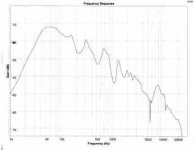
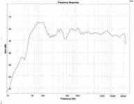
I have attached a near field on axis frequency response plot for my speaker. Note that the near field plot is only good up to about 700-1000 Hz so ignore the data above those frequencies. Furthermore, the true low end response of the speaker needs to be combined with near field port data which I will include in the next message in this thread.
The on axis performance plot shows a relatively smooth response within its validity limits. The on-axis data rolls off (starts below 80 Hz) on the low end and shows a dip in its slope below 50 Hz. The near field port data in the next message shows a peak in this same area. The port data will fill-in this on axis dip. Thus, the total response of the speaker is the acoustical combination of the on axis response and port response and it clearly creates performance below 50 Hz.
Bottom line is that this speaker performs very well as built and I would recommend that others would be successful in building it as well.
Dave (Planet 10) stated:
"It should be noted that GM's design is for a single driver & Jim has used 2... that Jim's box still turned out well is a testiment to how flexible an ML-TL is."
Let me reply:
From other posts by GM and by comparison to similar designs by others, I believe that GM's cross sectional area and length values are for two drivers. The remaining question is whether his port parameters are for a single or dual driver. Perhaps GM can chime in to clarify his box and port parameters.
Regardless of the above questions, the really question is just how well does this speaker that I built performs and whether the bass response is flat.
I have attached a near field on axis frequency response plot for my speaker. Note that the near field plot is only good up to about 700-1000 Hz so ignore the data above those frequencies. Furthermore, the true low end response of the speaker needs to be combined with near field port data which I will include in the next message in this thread.
The on axis performance plot shows a relatively smooth response within its validity limits. The on-axis data rolls off (starts below 80 Hz) on the low end and shows a dip in its slope below 50 Hz. The near field port data in the next message shows a peak in this same area. The port data will fill-in this on axis dip. Thus, the total response of the speaker is the acoustical combination of the on axis response and port response and it clearly creates performance below 50 Hz.
Bottom line is that this speaker performs very well as built and I would recommend that others would be successful in building it as well.
Attachments
Re: Measurements On Bipolar Speaker (On axis near field plot)
Jim,
You, me & GM already covered this off by private mail... GM comfirmss that his design is for a single driver. The data you provided at that time shows that it is actually big enuff to support 2 drivers and still give good performance.
dave
Jim Griffin said:From other posts by GM and by comparison to similar designs by others, I believe that GM's cross sectional area and length values are for two drivers. The remaining question is whether his port parameters are for a single or dual driver. Perhaps GM can chime in to clarify his box and port parameters.
Jim,
You, me & GM already covered this off by private mail... GM comfirmss that his design is for a single driver. The data you provided at that time shows that it is actually big enuff to support 2 drivers and still give good performance.
dave
One driver or two, I'd call that an excellent response. Looking at it, I don't think you'd get many more benefits from increasing the cross-sectional area. You might get a touch more bass, but the CSS drivers have a relatively high Fs anyway, so I'd be wary about pushing them too hard (though I really do fancy an array with them, or perhaps some similar Tang Bands, rolled off of course).
Cheers
Scott
Cheers
Scott
I find it a little hard to understand why one and two drivers would perform well in the same enclosure. Didn't some of you say that all the ported designs, be it BR or TL give you too much bass with FR125S? Is it like the hump at 100Hz which would be caused by the too small enclosure, or what do you actually mean by too much bass?
Greets!
Long story semi-short, JG contacted me soon after I posted these simmed designs http://www.diyaudio.com/forums/showthread.php?postid=672120#post672120 and apparently we got off the phone with at least one 'failure to communicate' (I thought I'd be receiving measured specs to fine tune the design, but never did AFAIK), and when he sent me an email asking for some clarifications, etc., to his initial design somewhat later on I missed it until finding it today, so he designed/built based on what info he had, and judging by the plots, it came out pretty good. Not that I'm surprised, his other ~FR driver designs I've auditioned literally were winners at some of the Atlanta DIY Meets.
FWIW though, here's my much belated thoughts on it:
I told Dave p10 in a PM awhile back that all the designs I posted in that thread were for a single driver since I hadn't specifically said they were for dual drivers, but after going back through all my info today I found that ideally they are for neither single or dual drivers per se, but dims of 'composite' sims I did (info from several different sims I did for both WR and FR series drivers to see what an averaged out design would look like), so the line length is 'close enough', the CSA is in theory much too large for one driver, but not quite large enough for two of either! Then there's the issue of what their actual specs are, though from JG's measurements and his 'thumbs up' approval of them, apparently the averaged design works quite well, so while it's probably not quite 'optimum', apparently it's 'close enough'.
WRT the vent, it's big enough for two drivers in a 'worst case' power scenario, so there shouldn't be any compression or vent noise problems.
WRT JG's stuffing comments in his pdf, apparently the pipe's Vb is a little low (CSA too small in this case) since he needed less stuffing to keep it from sounding too rolled off. This means a bit more uneven FR in the lower mids due to the large vent, but apparently it's not enough to be a problem.
He doesn't mention any damping in the 'spacer' cavity below the pipe, so maybe it's acting as a coupled resonant booster too. Still, I'm a firm believer in damping/mass loading any such cavities to ensure the sound is 'tight', though as always YMMV.
Anyway, sorry for all the confusion! If JG or anyone else has measured specs, then maybe the design can be fine tuned further if he's interested.
GM
Reply to GM's Comments and Measurement Discussion
Thanks GM for addressing the questions. My comments are below.
From your earlier design work that you sent me I realized that the numbers in your posting on this forum were not for a single driver so my design proceeded with the assumption that your values were for two drivers in the box. For what it is worth, the results demonstrated very good performance as shown in the measurements.
My stuffing of the box was as follows:
1. Upper third of the box. I used loosely filled with tufted Acousta Stuff from just below the drivers upward to the top of the box.
2. Middle of the box. Initially, I wrapped a batting of 2" thick fiberglass insulation around the walls of the enclosure for this portion of the box. After listening for a while I removed the fiberglass and noted that the bass seemed some better without the fiberglass batting in this area so I left it out.
3. Lower third of the box. No stuffing or batting in this portion of the box.
Bottom line is that the final speaker only has stuffing in the upper third of the box.
Measurement Discussion
A few comments on the measurements that I posted earlier in this thread. I included a near field on-axis plot which has most validity below 950 Hz for this size driver. This near field data can be combined with the port resonse if a correction based upon the ratio of the port and driver size is made. For the port data from these speakers the correction factor is about -3 dB so the port response should be lowered by this amount before combing with the near field plot.
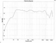
I have attached a plot of the on-axis in room (actually in my garage) frequency plot measured at 48" distance from one of the speakers. Note that the accuracy of this in-room measurement only extends down to about 300 Hz or so based upon the distance from the speaker and the measurement time window. The near field (corrected with the port data for the very lowest end of the band) and the in-room on-axis data can be spliced in the 300-700 Hz to create a total frequency plot for the speaker. I suspect that the dip about 450 Hz in the on axis room data is due to a bipole cancellation effect (in room interaction between the rear speaker and the front speaker) as it does not show this depth in the near field plot I posted above in this thread. Discounting the dip the overall data from 300 to 20,000 Hz is within a 6 (+/- 3 dB) window. The near field data (accurate below 950 Hz or so) is well within this same 6 dB window.
Overall the data are very impressive for this speaker and supports the listening tests that I have done.
I'll rescan the original measurement plots and send a set to Dave (Planet 10) to review and perhaps post if he sees fit. I regret the poor quality of the attachments but this forum only accepts a small sized file as an attachment.
Jim
Thanks GM for addressing the questions. My comments are below.
From your earlier design work that you sent me I realized that the numbers in your posting on this forum were not for a single driver so my design proceeded with the assumption that your values were for two drivers in the box. For what it is worth, the results demonstrated very good performance as shown in the measurements.
My stuffing of the box was as follows:
1. Upper third of the box. I used loosely filled with tufted Acousta Stuff from just below the drivers upward to the top of the box.
2. Middle of the box. Initially, I wrapped a batting of 2" thick fiberglass insulation around the walls of the enclosure for this portion of the box. After listening for a while I removed the fiberglass and noted that the bass seemed some better without the fiberglass batting in this area so I left it out.
3. Lower third of the box. No stuffing or batting in this portion of the box.
Bottom line is that the final speaker only has stuffing in the upper third of the box.
Measurement Discussion
A few comments on the measurements that I posted earlier in this thread. I included a near field on-axis plot which has most validity below 950 Hz for this size driver. This near field data can be combined with the port resonse if a correction based upon the ratio of the port and driver size is made. For the port data from these speakers the correction factor is about -3 dB so the port response should be lowered by this amount before combing with the near field plot.
I have attached a plot of the on-axis in room (actually in my garage) frequency plot measured at 48" distance from one of the speakers. Note that the accuracy of this in-room measurement only extends down to about 300 Hz or so based upon the distance from the speaker and the measurement time window. The near field (corrected with the port data for the very lowest end of the band) and the in-room on-axis data can be spliced in the 300-700 Hz to create a total frequency plot for the speaker. I suspect that the dip about 450 Hz in the on axis room data is due to a bipole cancellation effect (in room interaction between the rear speaker and the front speaker) as it does not show this depth in the near field plot I posted above in this thread. Discounting the dip the overall data from 300 to 20,000 Hz is within a 6 (+/- 3 dB) window. The near field data (accurate below 950 Hz or so) is well within this same 6 dB window.
Overall the data are very impressive for this speaker and supports the listening tests that I have done.
I'll rescan the original measurement plots and send a set to Dave (Planet 10) to review and perhaps post if he sees fit. I regret the poor quality of the attachments but this forum only accepts a small sized file as an attachment.
Jim
Attachments
Re: Reply to GM's Comments and Measurement Discussion
Up to 100k and a 1000 pixels wide. Lots & lots of room for FR plots -- we'll just have to teach you a few photoshop tricks.
Any low colour file such as a FR chart should be saved as a low bit gif (1-4 bits) -- never ever save as a jpg. A jpg is bigger & adds a lot of noise.
For instance the attached file (FR of FR125 & WR125 just to stay on topic) is 5 bits (because of all the colours), is way bigger than most FR plots being posted need be, and is still less than 25k.
dave
Originally posted by Jim Griffin I regret the poor quality of the attachments but this forum only accepts a small sized file as an attachment.
Up to 100k and a 1000 pixels wide. Lots & lots of room for FR plots -- we'll just have to teach you a few photoshop tricks.
Any low colour file such as a FR chart should be saved as a low bit gif (1-4 bits) -- never ever save as a jpg. A jpg is bigger & adds a lot of noise.
For instance the attached file (FR of FR125 & WR125 just to stay on topic) is 5 bits (because of all the colours), is way bigger than most FR plots being posted need be, and is still less than 25k.
dave
Attachments
Hello folks:
I built the ear level design and added a ribbon tweeter. I brought it down the Dave's in the summer for listening tests. I did not have the tweeter tuned in right so it was a little hot. The drivers were a little young. the over all impression was it was good but could nat take much power without flapping in the bass department.
They have since been worked in and I put a bit of resistance on the tweeter. They can be over driven in the bass at about 15 watts from my mini A.
Overall I think they are okay just tuned a bit too low.
I've had a careful read of the various bipole MLTL experiences with the FR125S. This sounds like the speaker for me - my last DIY speakers have done sterling service for the last 10 years, but I think its time for something new. And of course David at planet10-hifi.com and James Griffin and Martin J King have already put in most of the work ") .
.
I've modelled a solution using the quarter-wave.com sheets. I would appreciate the views of the resident geniuses on whether my parameters will be work in reality before I start cutting.
http://www.bigbrowncow.com/files/steves_bipole_MLTL.pdf
The dimensions allow for internal braces and a generous allowance for damping on the enclosure walls. All dimensions now in metric... It can also use a standard port, which will be in the base and downward facing with a couple of inches floor clearance.
With a bit of luck it could just squeeze F3 down to 40Hz - if I can squeeze out a bit more cross sectional area. It puts the centre of the speakers at ear level in sitting position, and I've got budget clearance from the wife!
Happy to post pictures and listening experiences as the project rocks unsteadily forwards.
Steve
.I've modelled a solution using the quarter-wave.com sheets. I would appreciate the views of the resident geniuses on whether my parameters will be work in reality before I start cutting.
http://www.bigbrowncow.com/files/steves_bipole_MLTL.pdf
The dimensions allow for internal braces and a generous allowance for damping on the enclosure walls. All dimensions now in metric...
It can also use a standard port, which will be in the base and downward facing with a couple of inches floor clearance.With a bit of luck it could just squeeze F3 down to 40Hz - if I can squeeze out a bit more cross sectional area. It puts the centre of the speakers at ear level in sitting position, and I've got budget clearance from the wife!
Happy to post pictures and listening experiences as the project rocks unsteadily forwards.
Steve
SCD said:.....the over all impression was it was good but could nat take much power without flapping in the bass department.
They can be over driven in the bass at about 15 watts from my mini A. Overall I think they are okay just tuned a bit too low.
Greets!
Bummer, apparently Adire 'robbed Peter to pay Paul' to get the high Xmax, leaving ~nothing left to Xsus/Xmech. Oh well, that's what 6th order alignments are for.
GM
- Status
- This old topic is closed. If you want to reopen this topic, contact a moderator using the "Report Post" button.
- Home
- Loudspeakers
- Full Range
- Bipolar MLTL Speaker with FR125S/WR125S