~1966 I made a 5 cubic foot enclosure for a 12 inch cast frame Allied Knight whizzer cone fullrange speaker (can't locate a catalog online) - think it sold for around $12.98 or 14.98, had a 1 1/4" vc, 20 ounce magnet,
my cabinet had 8 - maybe 10 - 3/4" holes bored in its baffle - sound was decent. (nothing to scare Henry Kloss) I then tried to tune it via duct and nomogram - just worse all around.
my cabinet had 8 - maybe 10 - 3/4" holes bored in its baffle - sound was decent. (nothing to scare Henry Kloss) I then tried to tune it via duct and nomogram - just worse all around.
Would it not be very similar or if not the same as using many small vents.
If your baffle is 3/4" thick and you are drilling 3/4" holes
You are basically making multiple round ports.
And you could calculate tuning with multiple round port equations.
The benefit seems if you wanted extremely low tunings
it would not require such long ports.
The tradeoff is like any round port, if you decrease the size/ vent diameter it requires less length
But a small port has extremely high velocity. So at higher power levels it is more likely to have chuffing.
In this case the Diameter is whatever size hole you drill.
And the Length is preset by the thickness of the baffle.
The number of ports used in the calculation is how ever many holes you drill
Using Example B from the article
which claims 6 cubic feet
Drilling 18 holes with .75" diameter
which would have a vent length of .75" if using 3/4 plywood
would yield a tuning of
54.2 Hz
6 Cubic feet
.75 inch holes ( vent diameter)
.75 inch baffle ( vent length )
18 holes 54.2 Hz
14 holes 47.8 Hz
10 holes 40.4 Hz
You can achieve even lower tunings if you drilled smaller holes, say .5 " instead of .75"
again the trade off is higher velocity. But lower tuning
6 cubic feet
.5 inch holes ( vent diameter )
.75 inch baffle ( vent length )
18 holes 38.6 Hz
14 Holes 34.1 Hz
10 holes 28.8 Hz
Last edited:

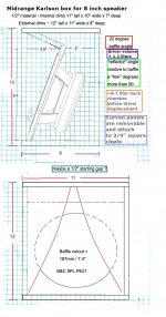
hi planet10 - what do you figure would be a good start for hole diameter - number and resistive material ? The rear chamber looks roughly 6 liters and lined with one layer of melamine "bricks". Maybe a brick would make a good hole damper.
(I probably should try to reduce that rear chamber w. rigid foam but kinda had to be like so to accommodate the leaning driver.)
(I probably should try to reduce that rear chamber w. rigid foam but kinda had to be like so to accommodate the leaning driver.)
Last edited:
I don't think so WhiteDragon.Would it not be very similar or if not the same as using many small vents.
The distributed port concept removes the need for tuning the enclosure. A DP enclosure behaves like a sealed enclosure, but with a reduced bass resonance peak. There is no double peak as is associated with a reflex enclosure.
The DP enclosure provides a form of aperiodic loading. Aperiodic literally means 'without period' i.e. without resonance. A truly aperiodic enclosure would completely eliminate the bass resonance peak.
Last edited:
it would depend upon how much "drag" the port array exhibits and some distributed port impedance curves would look like their reflex counterpart at small signal levels. As drive increases or significant cone movement from a "transient" occurs, the first peak would lessen and probably disappear at some point depending upon the hole or slot resistance vs drive level.
I had a nominal 4 cubic foot reflex box with removable port panel. I drilled 43 0.375" holes in a half inch plywood board. That tuned the box to around 50Hz. It was interesting that when the 15" Peavey woofer was fed around 10 watts, the air stream, like a fan, could be felt 10 feet away.
In experiments with a "small" 18 inch K-coupler and distributed slit vent, my friend said for acoustic music, he might prefer the distributed vent over a single vent of similar small signal tuning.
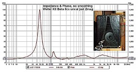
Here's small signal input impedance of a Beta 8cx speaker in a Karlson type, tuned with 5 - 6" by 0.375" slots. Its got a healthy first Z peak
I had a nominal 4 cubic foot reflex box with removable port panel. I drilled 43 0.375" holes in a half inch plywood board. That tuned the box to around 50Hz. It was interesting that when the 15" Peavey woofer was fed around 10 watts, the air stream, like a fan, could be felt 10 feet away.
In experiments with a "small" 18 inch K-coupler and distributed slit vent, my friend said for acoustic music, he might prefer the distributed vent over a single vent of similar small signal tuning.
Here's small signal input impedance of a Beta 8cx speaker in a Karlson type, tuned with 5 - 6" by 0.375" slots. Its got a healthy first Z peak
Attachments
Last edited:
freed sorry for the slow reply.
This is an image of the most advanced aperiodic box i have seen, i use the holes on the back as a reference.
I have used it successfully a couple times, this 4.5 litre FR125 box used similar. I did not get a picture of the holes, not in the plans (basic sketches).
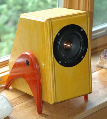
Hole size is somehwta dependent on how big the boc is. ⅜”, ½” on a grid similar to the PEARL, then damping pushed up against the holes on the inside. I use open cel foam. Thicker provides greate rdamping.
dave
This is an image of the most advanced aperiodic box i have seen, i use the holes on the back as a reference.
I have used it successfully a couple times, this 4.5 litre FR125 box used similar. I did not get a picture of the holes, not in the plans (basic sketches).
Hole size is somehwta dependent on how big the boc is. ⅜”, ½” on a grid similar to the PEARL, then damping pushed up against the holes on the inside. I use open cel foam. Thicker provides greate rdamping.
dave
A truly aperiodic enclosure would completely eliminate the bass resonance peak.
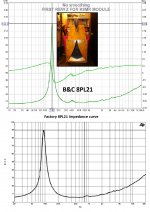
Here is a real-wold example;
dave
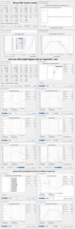
Is "this" a fair sim of a Klipsch Heresy I/K22 w. "variovent" and if so ?
will the response be elevated in the region of the center of the flattened impedance peak due to more current* being pulled ? (* ~constant voltage driving source)
I doubt if the damped vent would radiate much (??)
will the response be elevated in the region of the center of the flattened impedance peak due to more current* being pulled ? (* ~constant voltage driving source)
I doubt if the damped vent would radiate much (??)
Attachments
If the impedance graph with aperiodic vent were plotted on the same scale as the sealed case, it would be obvious by how much the single resonance peak is reduced in amplitude.
It would look like Dave's graph in post #31, and the dip in the centre that concerns you would not be so obvious.
You are correct that there would be little audible output from the resistive vent.
It would look like Dave's graph in post #31, and the dip in the centre that concerns you would not be so obvious.
You are correct that there would be little audible output from the resistive vent.
Usually when we are working with an aperidoic bass enclosure we are starting with a response near resonance that has a higher Q than we would like. If you are wholly successful with the aperidoic damping, then the response will be flattened, if not you will still have a bit of rise before roll-off.
The aperiodic vent dhould have little or no real output.
dave
The aperiodic vent dhould have little or no real output.
dave
I'll have to ask David McBean for how to set hornresp for these situations. Normally a Klipsch Heresy I with K22 isn't underdamped and the mod as I inputted is creating an underdamped output.
BTW - I put a Fane 250TC in a distributed 6-slit vent K12 with some bonded Dacron damping the slits - no adjustment - didn't do measurements, but the result had zero "boom' (also very little bass but the lack of boom and artifacts was welcome)
BTW - I put a Fane 250TC in a distributed 6-slit vent K12 with some bonded Dacron damping the slits - no adjustment - didn't do measurements, but the result had zero "boom' (also very little bass but the lack of boom and artifacts was welcome)
Last edited:
that sounds like a good idea. A box with a removable port panel is a good idea as can be fine - tuned during testing and when one is finished tuning, make a cosmetically acceptable version of the distributed (or damped distributive) port panel.
It would not be a bad idea either when building Karlson - type to have a removable port panel as to accommodate a larger variety of speakers and listener tastes.
It would not be a bad idea either when building Karlson - type to have a removable port panel as to accommodate a larger variety of speakers and listener tastes.
- Home
- Loudspeakers
- Full Range
- Whats the advantages of "Distributed Port" enlosure