Has anyone ever been successful with using an acoustic reflector? I recall the Bose 301 had that - with a dial on the cabinet you could adjust. However, I've never seen - besides attempts at omni - anyone use such a thing seriously.
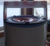
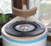
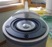
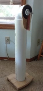
Being enamored at the moment with the sound of an upward facing driver in a stuffed pipe, I wondered what would happen if I was able to deflect a bit of the sound at a right angle - and towards me in at my listening position. The reflector to be placed in analog to where Linkwitz put the FR in his LxMini.
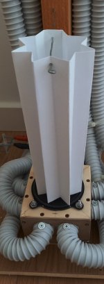
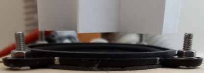
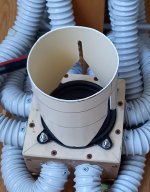
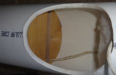
I started by attempting to make just the base plate to fit as a collar around the 4.5" tube, but I simply cannot make a machine-clean and square 4.5" hole in a 1" thick wood piece with the tools I have. So I soldiered on using material I can handle - a piece of plastic signage and a hot melt glue gun.
I'm getting soundstage at my listening position - plus whatever else this speaker configuration is doing that I seem to like. That's 90 degree off axis...
Is this tack worth pursuing? Or will any efforts be ultimately in vain, as no one has ever made a serious loudspeaker using such a device? It actually sounds pretty good for a first shot, giving me some hope.
I have a set of MA 3" drivers to try this on as well; as I read the 4" id tubes may be a little constrictive for the Pluvia 7 HDs.
Being enamored at the moment with the sound of an upward facing driver in a stuffed pipe, I wondered what would happen if I was able to deflect a bit of the sound at a right angle - and towards me in at my listening position. The reflector to be placed in analog to where Linkwitz put the FR in his LxMini.
I started by attempting to make just the base plate to fit as a collar around the 4.5" tube, but I simply cannot make a machine-clean and square 4.5" hole in a 1" thick wood piece with the tools I have. So I soldiered on using material I can handle - a piece of plastic signage and a hot melt glue gun.
I'm getting soundstage at my listening position - plus whatever else this speaker configuration is doing that I seem to like. That's 90 degree off axis...
Is this tack worth pursuing? Or will any efforts be ultimately in vain, as no one has ever made a serious loudspeaker using such a device? It actually sounds pretty good for a first shot, giving me some hope.
I have a set of MA 3" drivers to try this on as well; as I read the 4" id tubes may be a little constrictive for the Pluvia 7 HDs.
Attachments
For a few cents you can try this MDD3T240..
Post: https://www.diyaudio.com/forums/pla...idirectional-single-drive-17.html#post6613664
It does not use reflection but diffraction and deformation of the paper waveguide.
Post: https://www.diyaudio.com/forums/pla...idirectional-single-drive-17.html#post6613664
It does not use reflection but diffraction and deformation of the paper waveguide.
Attachments
The Jordan Aurora uses reflectors, not upward firing though. Not sure how successful a design it is but it's certainly interesting.
Jordan Aurora - E J Jordan Designs
This is a good read about omnis too in case you haven't seen it. I'm particularly enamoured with the Citation speaker, cool mushroomy phase plug thingy")
Omnidirectional speakers
Jordan Aurora - E J Jordan Designs
This is a good read about omnis too in case you haven't seen it. I'm particularly enamoured with the Citation speaker, cool mushroomy phase plug thingy
Omnidirectional speakers
These are both interesting replies - thank-you. I've put my Pluvia HD on a suprabaffle on my TABAQs to continue break-in. This frees up the "timedomain" pipes for experimenting with the CHN50s and vane designs. I'll continue to post replies here as things move forward.
Attachments
The advantage of the up-firing low frequency driver (as in the LXmini) is that non-linear distortion will be reduced at frequencies where the distortion products beam at the ceiling and are therefore heavily attenuated on-axis with the listening position.
The only reasons for using a up-firing full-range with a reflector would be that you're selectively directing the high frequency from only part of the cone surface to the listener - but you could also accomplish this with a phase shield and having the driver forward-firing.
The other reason is to place a cone shaped reflector in front of the driver to achieve omnidirectional high frequency radiation - or at least in the horizontal axis.
Last edited:
V1 Reflector
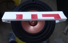
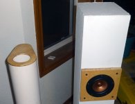
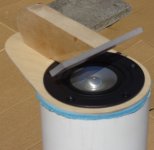
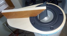
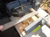
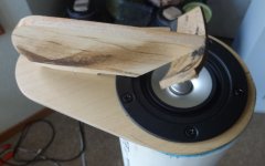
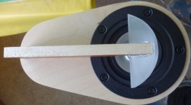
Generated a design to start off, basically a 1" wide piece of plexi at a 45 deg angle. I made the holder attach so you could slide it to various positions over the speaker cone.
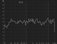
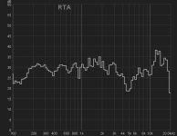
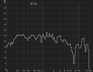
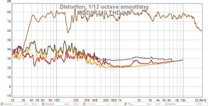
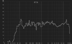
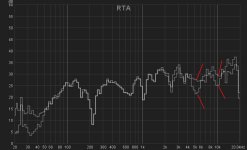
Measuring outdoors, 90 degrees off axis; 1st spectrum is with no reflector, second with the reflector covering just the rear half of the cone, third with the reflector structure covering most of the cone.
It was a very nice day and the single engine aircraft were out flying circles over my house, to help with my measurements.
I get the feeling that to completely eliminate the dip at 5kHz, the reflector will have to intercept all of the speaker cone area. Which takes the upfiring effects of this speaker design with it.
Looks like I'll need an acoustically semi-transparent reflector, to allow some of the sound to radiate on axis, some at 90 degrees. I have some perforated steel from the tweeter covers to a pair of radio shack linaeum speakers I salvaged...
Generated a design to start off, basically a 1" wide piece of plexi at a 45 deg angle. I made the holder attach so you could slide it to various positions over the speaker cone.
Measuring outdoors, 90 degrees off axis; 1st spectrum is with no reflector, second with the reflector covering just the rear half of the cone, third with the reflector structure covering most of the cone.
It was a very nice day and the single engine aircraft were out flying circles over my house, to help with my measurements.
I get the feeling that to completely eliminate the dip at 5kHz, the reflector will have to intercept all of the speaker cone area. Which takes the upfiring effects of this speaker design with it.
Looks like I'll need an acoustically semi-transparent reflector, to allow some of the sound to radiate on axis, some at 90 degrees. I have some perforated steel from the tweeter covers to a pair of radio shack linaeum speakers I salvaged...
Attachments
MDD3K240 Omnidirectional front acoustic load with triple Karlson profile
This device makes the emission of an upward facing driver omnidirectional. It works with diffraction and by changing the geometry you control the directionality and the frequency response.
MDD3A89
https://www.diyaudio.com/forums/pla...idirectional-single-drive-18.html#post6625965
This device makes the emission of an upward facing driver omnidirectional. It works with diffraction and by changing the geometry you control the directionality and the frequency response.
MDD3A89
https://www.diyaudio.com/forums/pla...idirectional-single-drive-18.html#post6625965
Attachments
V2
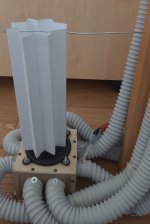
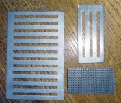
So I tried a few shots at a semi-transparent vane and none worked; even a piece of FR4 with PTHs drilled on a 1/10" matrix. It wants the reflector to be solid...
So to allow some of the sound to escape deflection and radiate upwards, my next tack is to make the reflector smaller. Here's what I've come up with - in the rough - and its corresponding 1 meter on_reflector_axis FR.
Since a metal mesh screen doesnt do a damn as a reflector, it can serve as a substrate for experimenting with different reflector shapes - provided those shapes cane be cut from a sticky back material - even a paper label.
I realize a bank-shot off a solid surface may not work out as well as a diffraction based device, such as a Karlson rocket or the profile claudiogan is suggesting. I'm open.
One of my design goals, if it's possible to achieve, is less of a "plumbing" appearance for the vertical tube speaker. So no caps, sleeves, 90 deg joints or rubber couplers with shiny hose clamps. Monolithic. Claudiogan's triple K tube has more potential for that than what I'm doing. I certainly wish the castle ends could stick up. And I have no idea where to even begin, except to grab a piece of tube and start cutting 'n measuring.
Attachments
Last edited:
That's very nice. It looks like it's upside down; my mind wants the Karlson curve part to be sticking up! Ah well, such is acoustics...what works acoustically is never the prettiest visually.
How many tries did it take you to get the triple K profiles to make that FR?
The first attempt I made with four K profiles and the closed side of the tube fixed to the driver. The closed bottom edge reinforces the frequency f = c / (Lmax * 4).
In the second attempt I moved the closed side up and the resonance disappeared.
In the third attempt I reduced the apertures from four to three, with the manual cut I always had a shorter tip than the others that did not touch the driver.
I think the two diffraction zones don't affect the frequency response.
The 20 mm thick upper closed loop has the purpose of reinforcing the frequency f = 341 / (2 * 20) * 10 ^ 3 = 8.5 KHz. It must be positioned at a height that allows to intercept the wave fronts of the frequencies to be reinforced. If reduced to less than 10 mm it should become neutral with respect to the frequencies emitted by the driver.
With such a low number of tests it is unlikely that my measurements are optimal for the 3FE25 driver. I don't know when I will do more tests.
Generated a design to start off, basically a 1" wide piece of plexi at a 45 deg angle. I made the holder attach so you could slide it to various positions over the speaker cone.
Measuring outdoors, 90 degrees off axis; 1st spectrum is with no reflector, second with the reflector covering just the rear half of the cone, third with the reflector structure covering most of the cone.
It was a very nice day and the single engine aircraft were out flying circles over my house, to help with my measurements.
I get the feeling that to completely eliminate the dip at 5kHz, the reflector will have to intercept all of the speaker cone area. Which takes the upfiring effects of this speaker design with it.
Looks like I'll need an acoustically semi-transparent reflector, to allow some of the sound to radiate on axis, some at 90 degrees. I have some perforated steel from the tweeter covers to a pair of radio shack linaeum speakers I salvaged...
You did not explain how to get the last freq. resp curve rather flat very different from the 1st two. Are the curves' responses change with respect to the angles of the reflector?
Explain please. Thks.
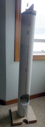
Sure! First, I placed the speaker outdoors in a generous space and drove it with pink noise (recorded on a mp3 file on a micro SD card which a small, mono class d amp plays automatically)
Second, I placed my Apex 220 measurement mic about a meter distant and 90 deg to the axis of the speaker driver, which is facing "up", at the end of a 1 meter, 4.5 inch PVC tube.
The first spectrum is what I get from this arrangement.
Next, I add a reflector, which attempts to ricochet some of the sound towards the microphone, off of a 45 degree angle. I placed it in a position that covered about 1/2 of the cone - and sounded good to me when listening.
The second spectrum is what I got from this arrangement.
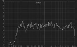
Finally, I moved the reflector forward (toward the mic) so it's fully centered over the driver cone. The third spectrum is what I got from this arrangement.
Second, I placed my Apex 220 measurement mic about a meter distant and 90 deg to the axis of the speaker driver, which is facing "up", at the end of a 1 meter, 4.5 inch PVC tube.
The first spectrum is what I get from this arrangement.
Next, I add a reflector, which attempts to ricochet some of the sound towards the microphone, off of a 45 degree angle. I placed it in a position that covered about 1/2 of the cone - and sounded good to me when listening.
The second spectrum is what I got from this arrangement.
Finally, I moved the reflector forward (toward the mic) so it's fully centered over the driver cone. The third spectrum is what I got from this arrangement.
Sure! First, I placed the speaker outdoors in a generous space and drove it with pink noise (recorded on a mp3 file on a micro SD card which a small, mono class d amp plays automatically)
Second, I placed my Apex 220 measurement mic about a meter distant and 90 deg to the axis of the speaker driver, which is facing "up", at the end of a 1 meter, 4.5 inch PVC tube.
The first spectrum is what I get from this arrangement.
Next, I add a reflector, which attempts to ricochet some of the sound towards the microphone, off of a 45 degree angle. I placed it in a position that covered about 1/2 of the cone - and sounded good to me when listening.
The second spectrum is what I got from this arrangement.
Finally, I moved the reflector forward (toward the mic) so it's fully centered over the driver cone. The third spectrum is what I got from this arrangement.
Noted and thanks.
I turned them into MLTLs, by placing a 100 X 10mm slot port at a 25" length and cutting an exit for the port radiation to easily escape. (Thanks to a design by Scott Moose for the CHN-50 inspiring me!)
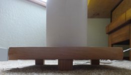
Dont have a wood lathe, but I do have a drill press and a big file. I was able to turn out a couple of 24mm wood pucks which I cut in half, then trimmed to make the port height. Glued in place.
Sweeping with my function generator, seems to have worked out pretty well. They have bass now. I'm seriously considering reducing them to appx 25" tall and having the port exit underneath the base, which will have to be spaced up off the carpet floor with feet.
I have them very lightly stuffed (~2.5 oz) with a "basket" keeping the stuffing up off and away from the port, about 2/3 length for the stuffing.
Up top there's a range of experiments to still do. A curved reflector. A different angle, say 60 deg (after reducing the height). A diffraction based lens. Even a 90 deg coupler (giving up on the upward facing driver) is still possible here.
The fun continues!
Attachments
Last edited:
Update
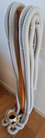
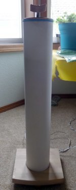
I shortened them to about 27" and arranged for the slot port to fire against the carpet exiting under the stands, which are raised on a triangle of 1" wood blocks. Trying to get the music to 'float above' the pipe ends with respect to two bedroom listening positions.
I also experimented with a curved reflector, which is just a hunk of old BR cardboard tube I had saved. FR (measured in the room) is different than the rectangular reflector and the upper mid dip persists. That's going to take some more design iterations to solve...
The original design of this 'time domain' speaker has a long metal rod attached to the speaker magnet, to give the driver something to push against, while its rim flange is softly coupled to the upper pipe edge. I'm going to give that idea a go - bye bye id sticker on the CHN-50 magnet.
Attachments
Something about your experiments tickled another memory.
This is an interesting one. Post #4
Cloning a $3200 Speaker for $400
This is an interesting one. Post #4
Cloning a $3200 Speaker for $400
Well, I spent $20 at home deep for a 60" length of 5/8 threaded rod and some nuts and 2" couplers. After removing the ID stickers, I glued the couplers to the CHN50 magnets...
The idea almost worked out, but the glue didnt dry after 24 hours - and probably a good thing it didnt. 2 lbs, 25" of 5/8 steel rod moment on the pole piece of this little 3" driver; lucky I didnt just twist the basket out of shape handling / trying to fit the assembly - stuffing spacer, stuffing and rod - into the tube.
Also didnt like the way it stuck magnetically to the magnet pole - both the coupler and the rod itself. I read the magnetic field cancelling magnets that get attached to speaker pole pieces dont effect things much, but I was wondering about it. I'll look for something non-ferrous and heavy to try next time. Maybe a big lead ocean fishing sinker... just a weight to put some significant mass to the driver pole piece.
I checked it off as "fail", with the good news that the rest of the project survived the attempt. Only loss was the driver ID stickers.
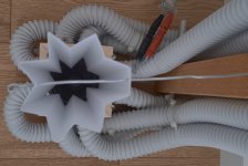
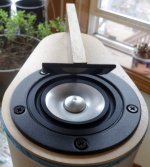
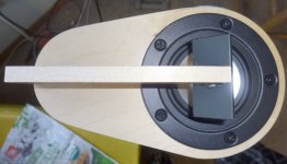
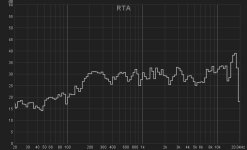
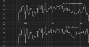
I've continued some empirical experiments using steel mesh (apparently nicely transparent acoustically) to which I can quickly and easily attach shapes cut from magnetic sheet. One particular parabolic shape gave a fairly decent frequency response within the 5 - 10K range, so I went with that to make a pair of more solid reflectors.
Photos show the reflector and corresponding FR for each speaker so equipped.
I'm pretty enamored with the way these throw sound into the gabled window space from a seated position about 15' away. Nice and deep, but not super precise imaging as they do when standing within the near field.
Thanks for looking!
Attachments
Last edited:
Configuration change
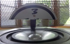
As this is basically a test bed, I had an inspiration from reading about the JBL lenses and how it was perceived they smeared the soundstage. My reflector design - also a lens of sorts - seems to me to have this shortcoming, which is just bothersome enough.
So it came to me that why not have the unmolested part of the speaker radiation facing forward and the reflected - and smeared - part facing up; versus the other way around? So here is that try -
Now it's easy enough to just remove the reflectors - and have an ordinary set of PVC pipe speakers...
Attachments
It's a nice summer day this afternoon, so I got around to taking one of these outside to do some measurements; the "up" reflector in place and rotated out of the way. It's not looking good for the reflector, in the only position that makes sense.
It's putting a couple of 5 db drops at 5 and 10 kHz in the forward projected sound, which means I'll probably throw in the towel on this idea - that of putting objects directly in front of a speaker's cone. I still like the up and front firing speaker idea, just probably with two acoustically unhindered speakers is a better way to go.
It's putting a couple of 5 db drops at 5 and 10 kHz in the forward projected sound, which means I'll probably throw in the towel on this idea - that of putting objects directly in front of a speaker's cone. I still like the up and front firing speaker idea, just probably with two acoustically unhindered speakers is a better way to go.
Attachments
- Home
- Loudspeakers
- Full Range
- In Vane? Or LxMini meets Bose 301...