i need help understanding my impedance curves.
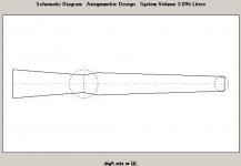
i simulated a tapered QWTL with hornresp then i made a quick and dirty build of the simulated design with construction grade plywood and screws. i sealed all the joints with the aluminum tape used for insulation and should be relatively sealed tightly.
its relatively close to the design, within an inch or so in length id assume and CSA is within close a deviation of a square inch or so along its length and the driver offset should be within an inch or less. i am converting from metric and stuff
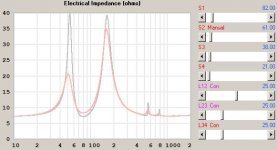
hornresp gives me a impedance peak at 46hz of just over 40 ohm and another at 200hz at just under 35 ohm. View attachment Hornrespimp plot.pdf
when i run the finished speaker on my woofertester i get a strange result
i cant post the screen shots at the moment i forgot to save them to somewhere i can share them from so i just have a picture of the computer screen.

confused with this i went back to hornresp and cant simulate it to look like the measured curve. i can get the peak height to be similar by shortening the line length but i cant get the peaks to move up in frequency to from 46hz and 200hz to 55hz and 150hz.
can someone explain what happened here and if i should try something to get the simulation to match the measured.
could it be speaker wire ? i used some cheap zip cord for testing ?maybe the speaker leaking i didn't do anything to seal that up its just the screws so im sure it leaks a little bit around the rough surface of the plywood.
i haven't pulled out a microphone to do any comparisons on that yet so i cant post them.
i simulated a tapered QWTL with hornresp then i made a quick and dirty build of the simulated design with construction grade plywood and screws. i sealed all the joints with the aluminum tape used for insulation and should be relatively sealed tightly.
its relatively close to the design, within an inch or so in length id assume and CSA is within close a deviation of a square inch or so along its length and the driver offset should be within an inch or less. i am converting from metric and stuff
hornresp gives me a impedance peak at 46hz of just over 40 ohm and another at 200hz at just under 35 ohm. View attachment Hornrespimp plot.pdf
when i run the finished speaker on my woofertester i get a strange result
i cant post the screen shots at the moment i forgot to save them to somewhere i can share them from so i just have a picture of the computer screen.
confused with this i went back to hornresp and cant simulate it to look like the measured curve. i can get the peak height to be similar by shortening the line length but i cant get the peaks to move up in frequency to from 46hz and 200hz to 55hz and 150hz.
can someone explain what happened here and if i should try something to get the simulation to match the measured.
could it be speaker wire ? i used some cheap zip cord for testing ?maybe the speaker leaking i didn't do anything to seal that up its just the screws so im sure it leaks a little bit around the rough surface of the plywood.
i haven't pulled out a microphone to do any comparisons on that yet so i cant post them.
Unless the driver is mounted external to your line, there will be a very large constriction at the OD in a pretty small line. That, coupled with very high box losses will make your impedance curve better approach what you have measured.
well i didnt think of that hmmmmm i wonder how i could build around that ? maybe some kind of back chamber of some sort
@GM changing ang only makes a small change to the impedance curve.
i cant find Rs anywhere can you push me in the right direction ?
i added to Rg to see what happens but nothing seems to change in the impedance graph.
had to edit the post to attach the export file
View attachment helixophile.txt
Last edited:
OK, didn't have HR loaded to check for myself. Rs = series resistance for many decades of use, but forgot HR lists it as Rg.
Regardless, grindstone probably 'nailed' it, so in your case, mount the driver on the outside of the baffle [frame out] for comparing to a sim since sound is 'round', the box is simmed as circular and the driver is nothing more than a flat disc with its depth only defined by its excursion [Xmax].
FWIW, modern drivers designed for acoustically tiny boxes [low Vas] ofttimes requires big vents as the design trade off when tuning around/at driver Fs, hence my preference for 'morphing' the box/vent to an inverse tapered TQWT of up to 20:1 compression ratio [CR].
In short, make the whole line larger [~4-10x Vas IME] or scale based on its 21 cm^2 terminus/vent for increased CR to both allow the driver to 'breathe' and increase its bass response; otherwise, if it already meets your performance goals in your app, then good to go as is.
OK, didn't have HR loaded to check for myself. Rs = series resistance for many decades of use, but forgot HR lists it as Rg.
Regardless, grindstone probably 'nailed' it, so in your case, mount the driver on the outside of the baffle [frame out] for comparing to a sim since sound is 'round', the box is simmed as circular and the driver is nothing more than a flat disc with its depth only defined by its excursion [Xmax].
FWIW, modern drivers designed for acoustically tiny boxes [low Vas] ofttimes requires big vents as the design trade off when tuning around/at driver Fs, hence my preference for 'morphing' the box/vent to an inverse tapered TQWT of up to 20:1 compression ratio [CR].
In short, make the whole line larger [~4-10x Vas IME] or scale based on its 21 cm^2 terminus/vent for increased CR to both allow the driver to 'breathe' and increase its bass response; otherwise, if it already meets your performance goals in your app, then good to go as is.
im open for improvements ive just followed the steps ive read about here and beat on the keyboard with hornresp until it was smooth for as wide of a bandwith as possible
so your saying keep the 21sqcm vent and make the rest of the pipe larger but put the vent at the large end ? like the frugalhorn? thats what i think is what your saying ?
i did stuff the box but nothing to scientific i put a strip of cotton from the craft store where they sell polyfill around the walls of the box at the large end and a strip of polyfill in the middle to roughly the depth of the driver. my simulation isn't great but it got really smoothed out when i added stuffing to it so i tried to start simple and see what happens from there.
@Dave what does pushing it aperiodic mean ? All i remember about aperiodic vents is that they used to get used in small box woofer car audio back in the 80s and early 90s they essentially made a leaky sealed box, making the woofer preform like its in a larger box than it is in. Is my vent so small that its not preforming correctly ?
the box is 30" tall and about 6" external width with only one bend right at the vent end making the vent point forward instead of down. the vent it just under 3/4" tall by the 4.5" wide internal width.
thanks again guys these posts send me down a week long rabbit hole reading every post that mentions anything in any of your responses.
I implied my comment from the shape of the curve.
My miniOnkens measure similarily, the vents are purposely long, wide & narrow to increase resistance of the vent — they can be pushed more & more aperidoic by inserting something resistive in the vents. You can do the same — essentailly what Ted’s ARU, dyna A25, and the Scan variovent, but not with as much fine control.
dave
so your saying keep the 21sqcm vent and make the rest of the pipe larger but put the vent at the large end ? like the frugalhorn? thats what i think is what your saying ?
i did stuff the box but nothing to scientific i put a strip of cotton from the craft store where they sell polyfill around the walls of the box at the large end and a strip of polyfill in the middle to roughly the depth of the driver.
You're welcome!
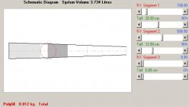
No, just start at its terminus [vent opening in the sense that the whole pipe IS the vent] since we normally want a vent area [Av] that's at least 25% of [Sd] and with higher power/Xmax drivers it can require an [Av] = [Sd].
IOW a 'faster' expanding pipe than what you currently have or if you want the same taper as the existing one, just increase [S1], [S4] by the same multiplier to get a large enough volume [Vb] up to as much as [S4] = [Sd] to fit the driver with some 'breathing' room.
OK, guess that's 'close enough' to what was simmed, though recommend that damping be in the driver area to keep any reflections modulating the diaphragm, combing filtering with its output [adding out of phase harmonics].
Last edited:
if it matters anymore
H - Back to your original thrust for a minute, just had a look & you may have closer than you think. HR is a 1-dimensional sim, so 15 or 20% is a win but it seems common lately for expectations to be high. +1 to the previous replies as well.
If starting with the OD where you built it and close sizes, your hump locations should line-up pretty well in HR in my exp. Using your export, they mostly do (maybe 53 & 163Hz vs. 55 & 150) w/o any real detail and with an empty line! OK, your curve screams some sort of loss, so here's a hack at your polyfill:
Tracks better. Again, w/ a 1-D model and about zero detail. Yes, still issues but, if you recall earlier difficulty attempting to make HR humps conform to your target, this is actually comforting insensitivity
It's almost never possible to model Exactly what you want in HR, but it's almost always possible to get something useful. How much you want out of it is your call. You can vary HR geometry until bleery-eyed and lots of geometries are possible and valid.
If it matters a bunch, maybe bang on an OD VB and twiddle both the QL (1 is a sieve, 99+ lossless) and stuffing. Not to mention geometry. Tough to guess how much to choke the geometry not knowing your driver info. If you add the same stuffing to this HR record as the prev attachment, it should look a bit better (forgot image & other machine).
Oh--reminds me--you mentioned accounting for that volume earlier. Lots of people put a 90 or a 180 at the OD to aid offsetting driver region area reductions. Brian Steele at diysub used to have some spreadsheets that crunch some of those geometries for canned packaging solutions FWIW.
Attachments
grindstone
thanks i see that now it seems that the restriction of the driver in the small CSA could be an issue.
modeling and reality are hard to correlate sometimes, i see that now.
ive done all of my previous designs based on ported or sealed enclosures and they seem to be much more forgiving as much of the stuff is based on volume alone.
ill get more info on the driver along with pictures posted soon a few things have been holding me up but when i had a few hours to run into the garage and cut up some wood i jumped on it
i think there is some leakage around the drivers basket i will try sealing that up and also flip the drive around to see what happens. my guess is i learned a valuable lesson on how to use simulations.
the sheer amount of information on the subject is sometimes frustrating i spend hours reading posts and following things i find in responses and googling them, sometimes its an AHAH moment mostly its a rabbit hole.
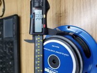
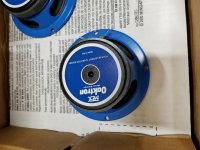
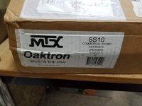
its an mtx oaktron
Yes, saw it, but normally there's more info on the label and/or driver proper..........
GM
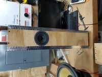
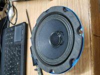
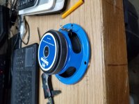
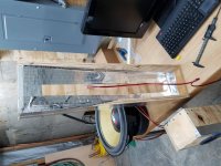
sorry i don't have much info here is a few pictures of them
and the completed test enclosure
sorry i don't have much info here is a few pictures of them
and the completed test enclosure
Attachments
- Status
- This old topic is closed. If you want to reopen this topic, contact a moderator using the "Report Post" button.
- Home
- Loudspeakers
- Full Range
- tqwtl impedance curve comparrison